How to tune the R PRO-1 using Home Assistant
Your R PRO-1 has two unique mmWave sensors that both need to be tuned!
The R PRO-1 comes with an LD2450 mmWave sensor and an optional secondary LD2412 mmWave sensor.
The LD2450 allows for up to three targets tracked in up to three zones but can have issues with "still detection".
The optional LD2412 mmWave sensor allows you to have perfect still detection for one target at up to 9 meters so it's a great addition to the sensor.
Prefer a guided dashboard?
The Apollo mmWave integration gives your R PRO-1 a dashboard tab where you draw LD2450 zones over live targets and tune the LD2412 gates with a Calibrate with empty room button. The Apollo mmWave dashboard guide walks you through it as a guided alternative to the manual steps below. If you draw zones there, leave LD2450 Zone Type on Disabled instead of entering zones below: the dashboard's zone map replaces the radar's built-in zones, and its Radar setup card offers Set Zone Type to Disabled when it isn't. To keep a fan or a curtain from turning those zones on, draw an ignore zone over it on the map.
Manually enter in the X and Y coordinates for each zone in Home Assistant or directly from the device's webserver by visiting the IP address or hostname.local. It's much easier to tune using the HLK Radartool App and we suggest using that to set up your R PRO-1 LD2450.
LD2450 configuration
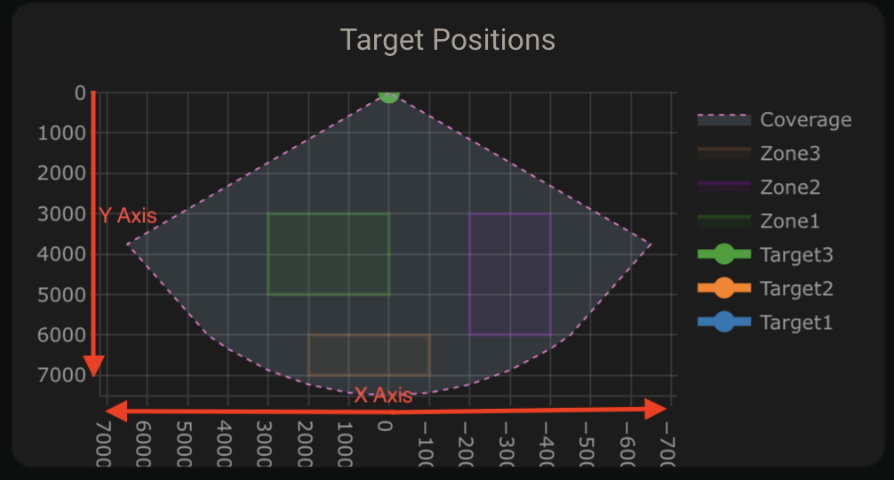
Follow these steps to add a Plotly card that shows your LD2450 targets, then set up your zones in Home Assistant.
1. Install HACS.
2. Download Plotly inside HACS.

3. Enter your device’s full name and optionally customize the names of the three zones using the tool below. Then click Generate YAML and Copy YAML.
If you're unsure of your device name, go to Settings → Devices & services → ESPHome, select your device, and look for the full name. Unless you’ve renamed it, it will likely be something like "apollo_r_pro_1_eth_593904", with six random characters at the end.
4. Head to a dashboard view and click the pencil icon to edit dashboard then click one of the large "+" signs, type in manual, and click on it.
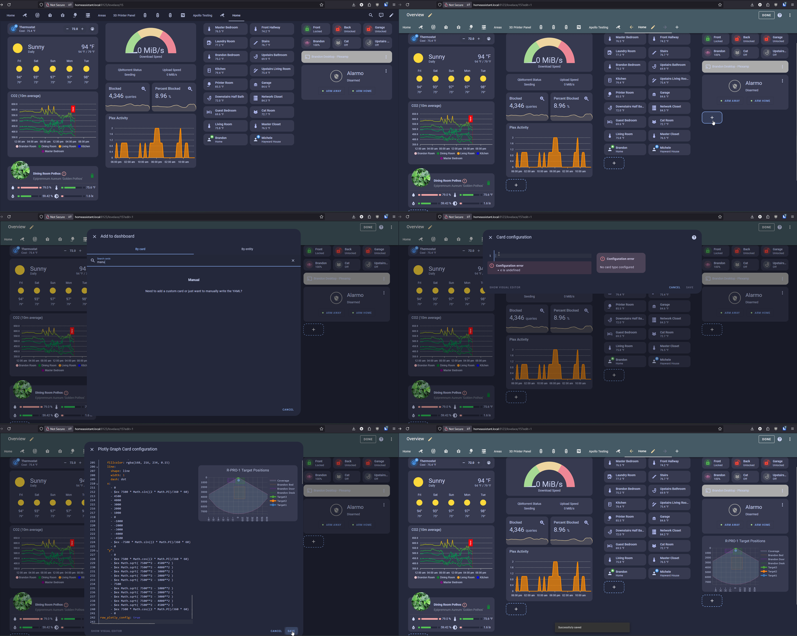
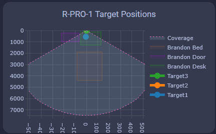
5. Delete any text in the custom card then paste the YAML you copied above and click save when finished. You should now have a custom card that looks like the card below!
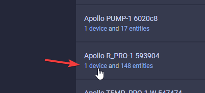
6. Head to the ESPHome integration page (Settings → Devices & services → ESPHome).

7. Click device as shown in the image below
8. Scroll down until you get to the Configuration section and you see the empty boxes for zones 1-3 for both X and Y coordinates.
Suggested settings
- Multi Target Tracking toggled on helps it detect up to three targets better.
- Zone Type allows you to select Disabled, Detection, or Filter.
- Disabled: Disable zone area detection.
- Detection: Only detects targets in the specified zone. With no zones set, it detects nobody.
- Filter: Excludes a zone from detection.
9. Now we can input our Zone 1-3 X and Y values to make our zones. Using the visual card from above, we can walk, sit, or stand in the area where we want to create a detection or non-detection zone. Input values for X are -4860 mm to 4860 mm, and the Y values are 0 mm to 7560 mm.
Helpful Hints to understand zones better!
-
X1 must always be less than X2, and Y1 must always be less than Y2.
-
The Y axis is easier since it's never negative.
- The X axis is where you can get tripped up, especially when both values are negative: -3456 is less than -2345.
- The Plotly chart will still render the rectangles even if the X1/X2 and Y1/Y2 values are reversed.
- The zones cannot overlap.
Apollo mmWave does this for you
With the Apollo mmWave integration 2.4.0 or newer, you can skip steps 10 to 13. Apollo mmWave shows your R PRO-1's Target X and Y in mm on its own: on a new R PRO-1 as soon as you add it, and on one you already had once, after Home Assistant starts, with the notification Apollo mmWave: Target X and Y now in mm. It leaves alone a sensor whose unit you picked in its settings, which you change there, and one that an automation, a script, or a helper uses. For a sensor in use, first change any number it's compared to into mm, 25.4 times as large, then, as an administrator, press Show Target X and Y in mm on the Radar setup card above the zone map. The button switches only sensors whose unit Home Assistant picked on its own, never one whose unit you picked. To go back to inches, choose in under Unit of measurement in the sensor's settings. The Apollo mmWave dashboard guide has the details.
10. If you use the imperial system (Freedom Units) then you will need to do this step. Metric users can skip this. For the targets to show up correctly we first need to update the Target 1-3 X and Y measurements from inches (in) to millimeters (mm). Find Target 1-3 X and Y under the Sensors section and select them. You will want to update all 3 X and Y target values.
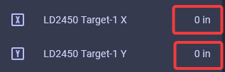
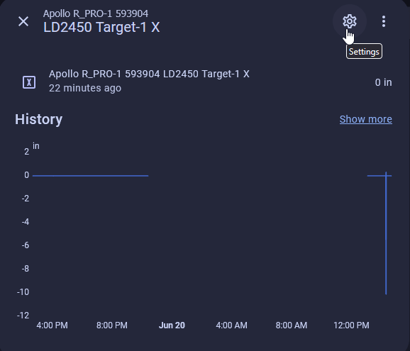
11. Select the Settings cog in the top right.
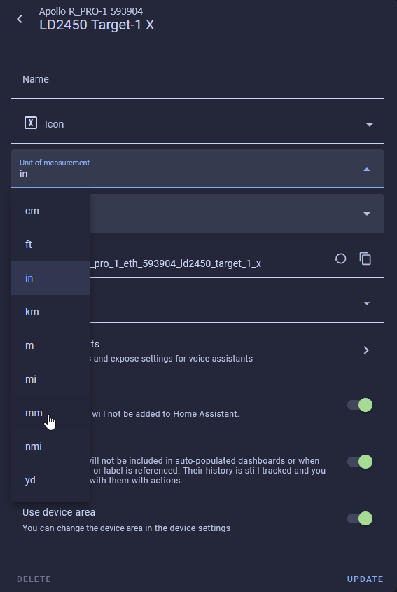
12. Change the unit of measurement to mm and select Update.
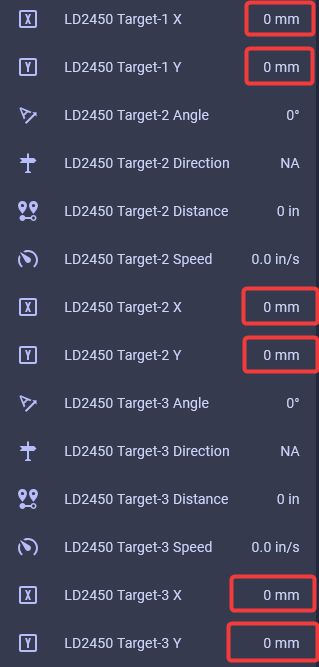
13. Your X and Y Targets will now look like this.
14. Now you should see targets on the card.
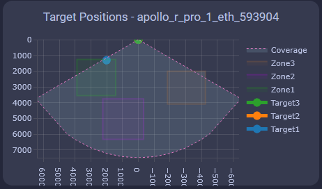
15. Now we can make zones around the targets where you want to Detect presence or filter them out.
Tip for zone configuration resetting
If your zone configurations are not saved when restarting the device then try turning on the LD2450 Bluetooth for a few seconds and then turning it off again. You can also try toggling on LD2450 Multi Target Tracking. This should wake up the mmWave module and retrieve your saved zones
LD2412 configuration
Follow these steps to switch the LD2412 to Engineering mode and tune its gates in Home Assistant.
1. Go to Settings → Devices & services → ESPHome and click 1 device below the Apollo R PRO-1.
2. Scroll down until you see "LD2412 Mode" and change it from "Normal" to "Engineering".
The LD2412 can be tuned using the steps below to work perfectly in your environment!
The LD2412 has "gates" at 0.75 meter increments starting at g0 and ending at g13. These gates allow you to raise the threshold needed to trigger occupancy in each 0.75 meter increment.
This is very useful in scenarios where you want to tune out a fan, a cat sitting on the stairs, etc.
3. Scroll down to the Diagnostic section and you will see "LD2412 g00 move energy" through "LD2412 g13 still energy" are showing percentages from 0-100%.
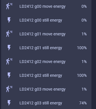
4. Scroll up to the Configuration section and identify the threshold sliders for g0-g13 for both moving and still energy.
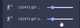
Moving the gate still and move threshold slider to the right increases the amount of energy needed to trigger the sensor. Do this if you want the gate to be less sensitive.
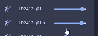
Moving the gate still and move threshold slider to the left decreases the amount of energy needed to trigger the sensor. Do this if you want the gate to be more sensitive.