Adding the LED & Buzzer Module
The LED & Buzzer is the starter kit's notification module, a strip of ten addressable RGB LEDs and a small piezo buzzer behind the ESPHome logo silkscreen. By the end of this tutorial you'll have the lights and buzzer wired to your ESP32-C6, surfaced in your YAML, and ready to flash, animate, or sing in response to anything else you build.
Before you start
Work through the two prerequisites first:
- Start Here to snap the RGB & Buzzer module off the panel.
- First Steps to install ESPHome Device Builder and create your starter kit device.
Attach LED & Buzzer module
Connect the LED & Buzzer module to the ESP32-C6 using one of the FPC ribbon cables that came with the kit. Either FPC connector on the ESP32-C6 works, top or bottom.
1. Unplug the USB-C cable from the ESP32-C6 so it is powered off.
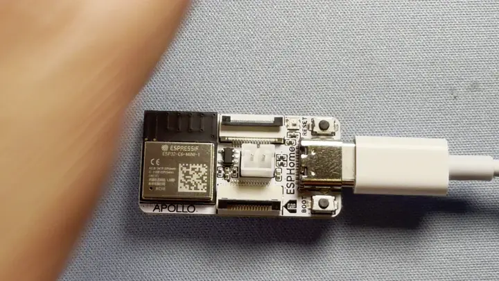
Handle the FPC connectors gently
The latches are small and the ribbon cable is fragile. Lift the latch with a fingernail, slide the cable in, and press the latch down. Never pull on the cable itself.
2. Flip up the latch on the FPC connector then gently slide the ribbon cable in to the connector with the blue side facing upwards. Gently press the latch down to lock it in place.

3. Slide the ribbon cable into the LED & buzzer module with the blue side facing upwards then press the latch down to lock it in place.
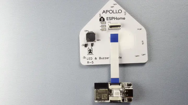
4. Plug the ESP32-C6 back into your computer.
Add to ESPHome Device Builder
ESPHome Device Builder ships an Add Component flow that knows the pin layout for every Apollo Starter Kit module. Use it instead of writing the LED strip and buzzer config by hand, and you'll get the right GPIOs, chipset, and PWM setup on the first try.
- Open your starter kit device in Device Builder and click Edit.
- In the ESPHome Device Builder, navigate to the Components section.
- Click Add Component in the editor toolbar.
- Select the RGB LED + Buzzer Module Bundle at the top.
- Click Add -> Click Add -> Click Add -> Click Add. Each section lets you make changes but we will leave them at defaults for now. Device Builder inserts the light, output, and rtttl blocks into your YAML.
What the LED & Buzzer Module YAML does
The blocks Add Component drops into your config look like this:
light:
  - platform: esp32_rmt_led_strip
    name: RGB LEDs
    pin: 14
    id: rgb_leds
    chipset: WS2812
    num_leds: 10
    rgb_order: GRB
    rmt_symbols: 48

output:
  - platform: ledc
    pin: 18
    id: buzzer_output

rtttl:
  - output: buzzer_output
    id: rtttl_player
Each option does something specific:
| Option | What it does |
|---|---|
| LED strip | |
light.platform: esp32_rmt_led_strip |
Uses the ESP32's RMT peripheral to drive addressable LEDs with precise timing. |
light.name: RGB LEDs |
The friendly name shown in Home Assistant and the web server. |
light.pin: 14 |
The data line (GPIO14) going to the first LED on the PCB. |
light.id: rgb_leds |
Internal handle you can reference from automations and lambdas elsewhere in the config. |
light.chipset: WS2812 |
Which addressable LED protocol to use. WS2812 is the most common, sometimes also called NeoPixel. |
light.num_leds: 10 |
The number of LEDs on the RGB & Buzzer module. |
light.rgb_order: GRB |
Color channel order. WS2812 LEDs receive color data in green-red-blue order, so this makes sure red looks red and not green. |
light.rmt_symbols: 48 |
Low-level RMT setting needed on the ESP32-C6. Leave it at 48. |
| Piezo buzzer | |
output.platform: ledc |
PWM output for driving the buzzer. PWM is how digital pins create audio tones on a piezo. |
output.pin: 18 |
The pin the buzzer is wired to (GPIO18). |
output.id: buzzer_output |
Internal handle the rtttl component uses to send tones to this output. |
rtttl.output: buzzer_output |
Tells rtttl to use the buzzer output for playback. |
rtttl.id: rtttl_player |
Internal handle for triggering tunes from automations and lambdas. |
Install the firmware
Flash the device so the new RGB & Buzzer entities go live.
- Click Install on your device card in ESPHome Device Builder.
- Choose Plug into the computer running ESPHome Device Builder for the first flash, or On The Network if the device is already on your Wi-Fi.
- Wait for the compile and flash to finish. First builds can take a few minutes.
- The device reboots and reconnects to your Wi-Fi on its own.
Test the LEDs
With the device back online, the RGB LED light entity is live on the web server. Open it in a browser on the same network and play with it.
- In a browser, open
http://<your-device-name>.local/. If you usedesphome-starter-kitas the device name in Getting Started, that'shttp://esphome-starter-kit.local/. - Toggle the RGB LEDs entity and play around with the colors and brightness. (1)
- There's a lot you can do with a light entity. See the Light Effects tutorial for advanced configurations, or the ESPHome light strip effects documentation to go deeper.
Your LED & Buzzer notification module is wired up!
Your LED & Buzzer Module is now ready for some fun tasks, like toggling lights on and off, playing with the colors, or using the buzzer to play fun tunes!
The buzzer doesn't have its own web server control, since it's an output rather than a switch. Once you've added the device to Home Assistant, you can trigger tunes with the rtttl.play action or by exposing your own service. See Play a Tune from Home Assistant to learn how to set it up.
Try it in an automation
Your notification module is ready. Drive it from any of these automations:
![]() Button Controlled LEDs
Button Controlled LEDs
![]() Play a Tune
Play a Tune
![]() Temp-Reactive LEDs
Temp-Reactive LEDs
![]() Motion-Activated Light
Motion-Activated Light
New to ESPHome? We're here to help.
Stuck on a step or want to show off what you built? Ask questions and share projects with the Apollo community.