BTN-1 GPIO pinout
The BTN-1 has two GPIO headers on its circuit board: a 10-pin header on the side and a 16-pin header on the top. Use these maps to wire extra sensors, LEDs, or other hardware to your BTN-1 and to find the GPIO numbers you need in ESPHome.
Open the case to reach the headers
The headers are on the circuit board inside the case. Follow Teardown and reassembly of BTN-1 to lift out the board, and flip the battery switch off first if your BTN-1 has a battery.
Side header
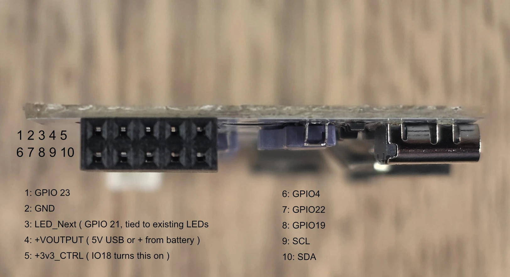
The table below is laid out like the header in the photo, with pin 1 at the end farthest from the USB-C port.
| Row | |||||
|---|---|---|---|---|---|
| Nearest the board | 1 GPIO23 | 2 Ground | 3 LED_Next (GPIO21) | 4 +VOUTPUT | 5 +3v3_CTRL |
| Outer | 6 GPIO4 | 7 GPIO22 | 8 GPIO19 | 9 SCL | 10 SDA |
- LED_Next is tied to the BTN-1's existing LEDs.
- +VOUTPUT is 5V from USB, or + from the battery.
Top header
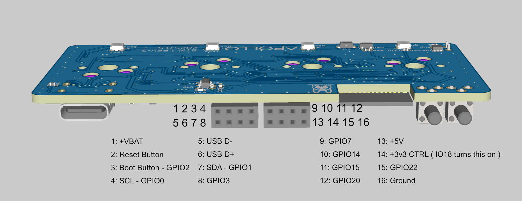
The top header is two blocks of eight pins, laid out below like the header in the image.
Block nearest the USB-C port
| Row | ||||
|---|---|---|---|---|
| Nearest the board | 1 +VBAT | 2 Reset button | 3 Boot button (GPIO2) | 4 SCL (GPIO0) |
| Outer | 5 USB D- | 6 USB D+ | 7 SDA (GPIO1) | 8 GPIO3 |
Block nearest the buttons
| Row | ||||
|---|---|---|---|---|
| Nearest the board | 9 GPIO7 | 10 GPIO14 | 11 GPIO15 | 12 GPIO20 |
| Outer | 13 +5V | 14 +3v3_CTRL | 15 GPIO22 | 16 Ground |
+3v3_CTRL is switched
The +3v3_CTRL pin on both headers only has power while GPIO18 is on. If something you power from it stays off, check that GPIO18 is on.