Control an LED strip with the GPIO Header
The GPIO Header addon brings the AIR-1's spare pins out to a row of headers, so you can hang your own hardware off the sensor. This guide wires a WS2812B strip to one of those pins and gets it into Home Assistant as its own light entity, color picker and effects included.
Click any photo to see it full size.
What you need
- An Apollo AIR-1.
- The Apollo GPIO Header addon, which ships with a replacement AIR-1 lid.
- A WS2812B (neopixel) RGB strip. SK6812 RGBW strips work too.
- Three male-to-male DuPont wires. A set comes with the header.
- A USB-C cable and power brick.
Watch the current draw
The 5V pin supplies up to 300mA. A meter of 60 LEDs at full white draws far more than that, so anything longer than a short strip needs its own 5V supply. You can power the AIR-1 itself from the 5V and GND pins instead of the USB-C port, but use one or the other, never both.
Choosing a data pin
IO2, IO4, IO6, and IO7 are free for LED data, and you can drive more than one strip by giving each its own pin. IO18 and IO19 are unavailable, and IO0 and IO1 are reserved for I2C sensors. This guide uses IO7, plus the 5V and GND pins at the top of the header for power.
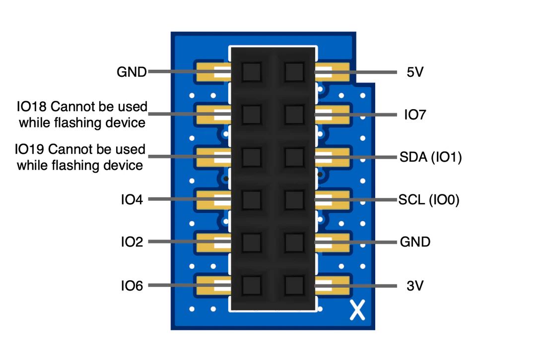
Attaching the GPIO Header
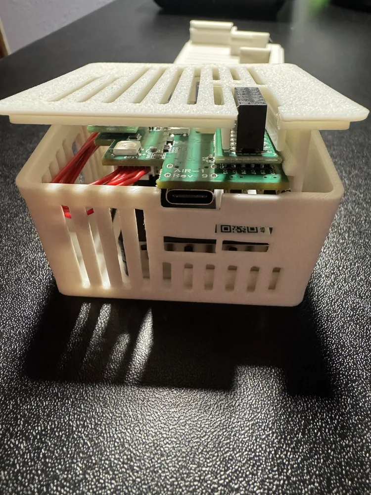
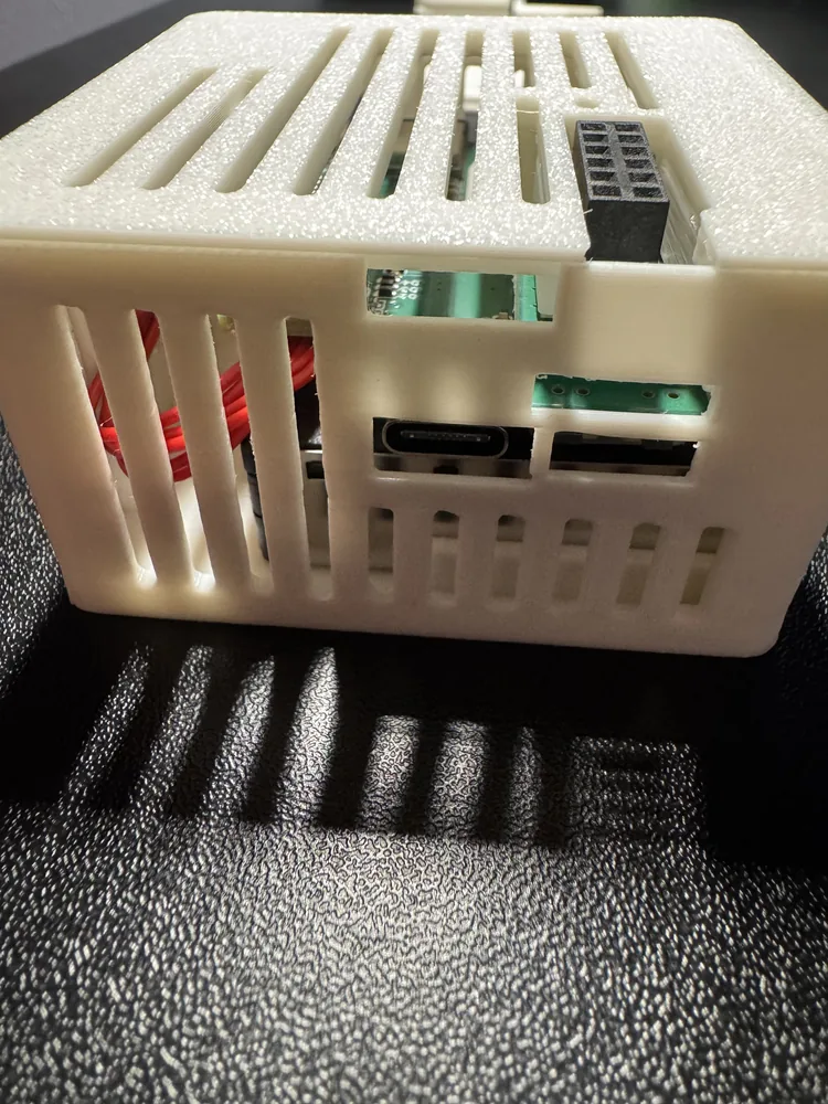
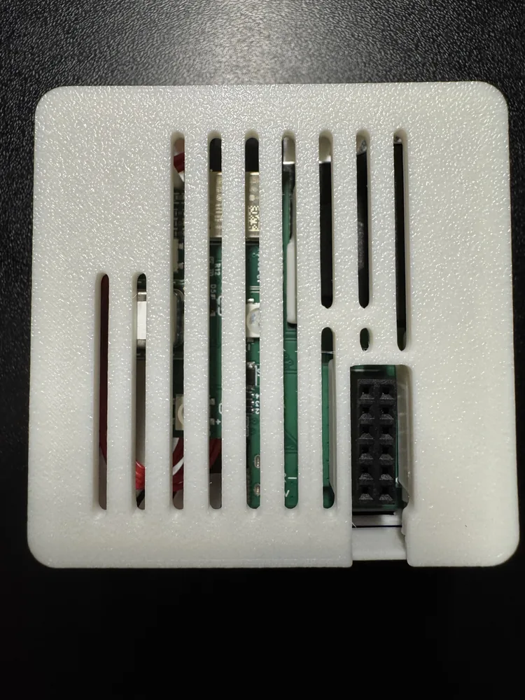
Opening an AIR-1 takes a few more steps than the other Apollo sensors, because the PCB slides out of the case. The GPIO Header addon page has photos of each one.
-
Unplug the AIR-1, lift the lid off, and slide the PCB out to the left.
-
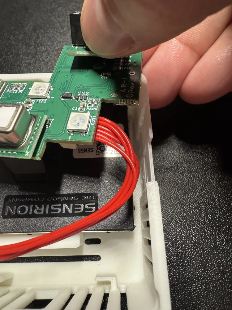
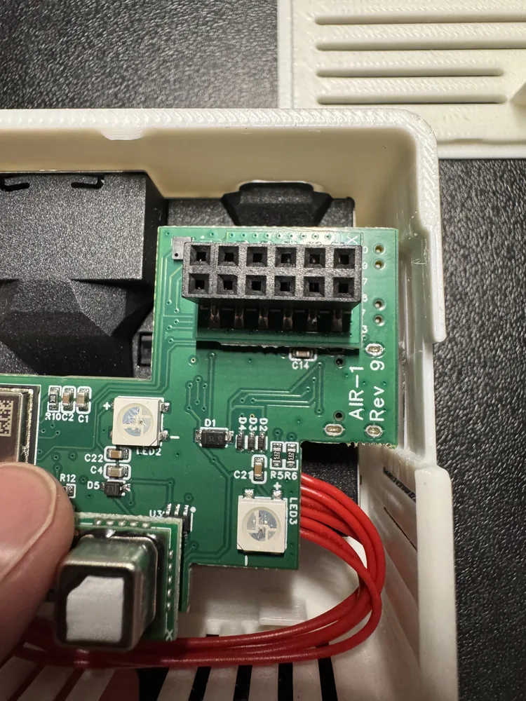
Flip the PCB over and find the small black mezzanine connector in the top right corner. An X marks the corner, and the GPIO Header has a matching X on its own board.
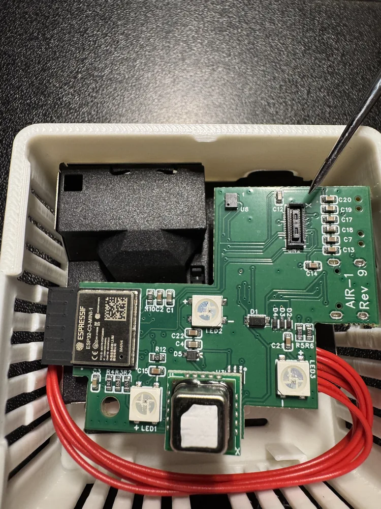
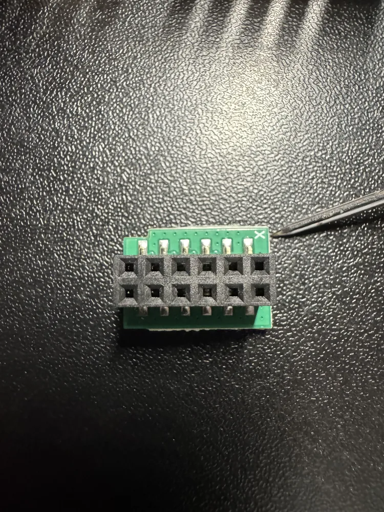
-
Line the two X markings up and press the header gently onto the connector.
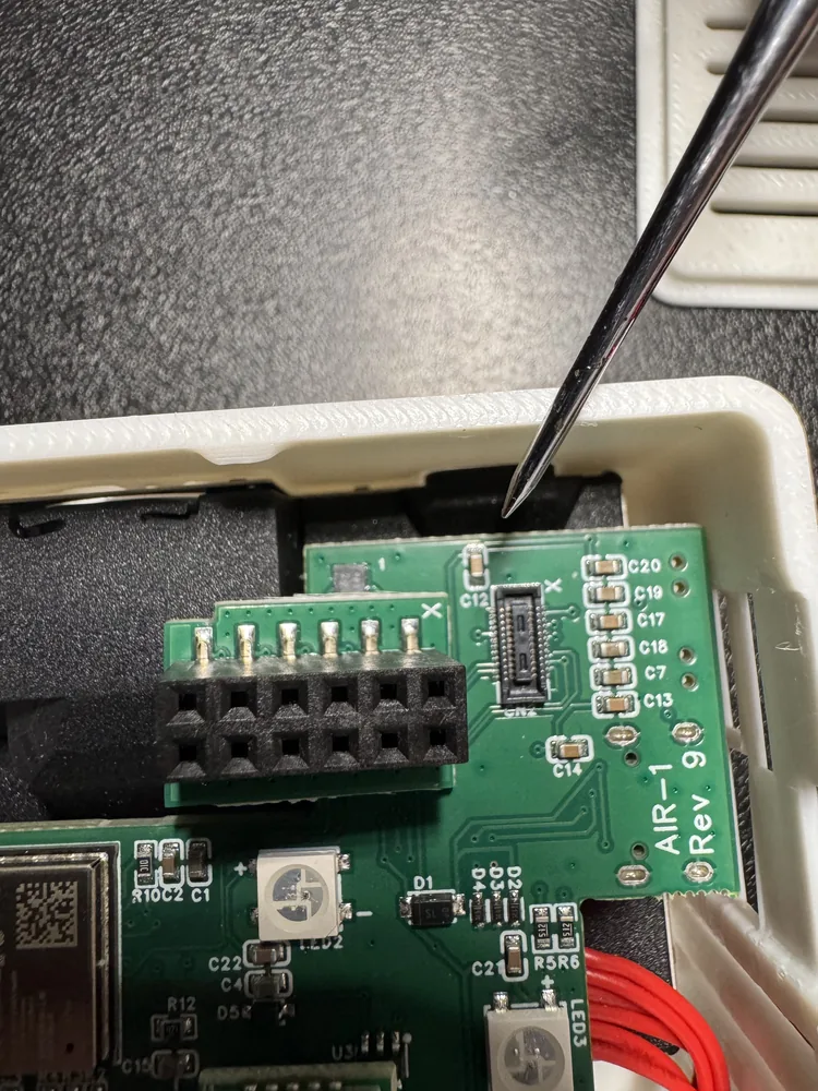
-
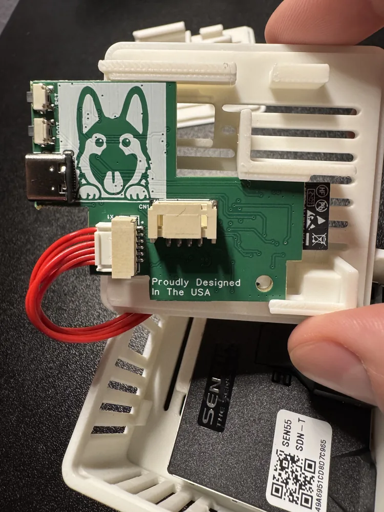
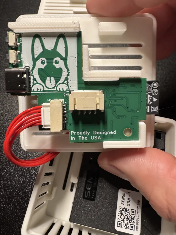
Flip the PCB back over and slide it into the new lid that came with the addon. There are three channels in the plastic for it to run in, so it should go most of the way with light pressure.
-
Push the case back together.
Wiring the strip
-
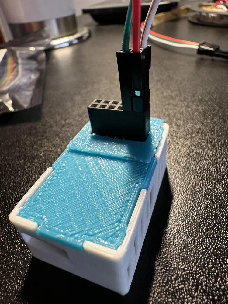
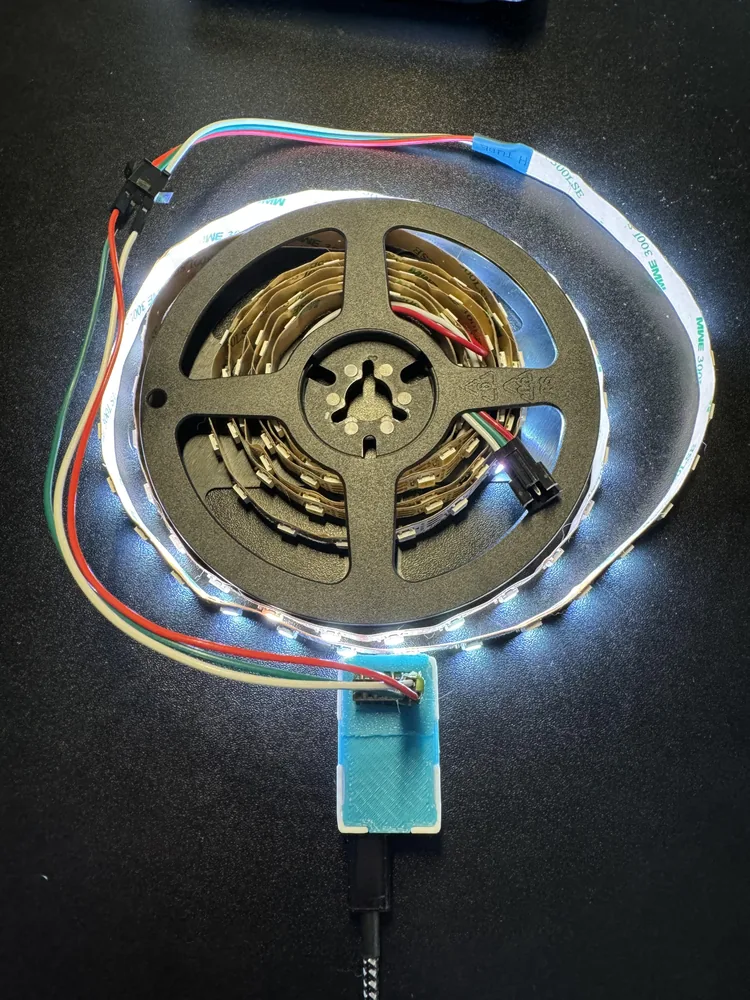
Run three wires from the header to the strip: 5V, GND, and data. Matching the colors to the strip's own wiring saves a lot of squinting later, so use red for 5V, white for GND, and green for data on IO7.
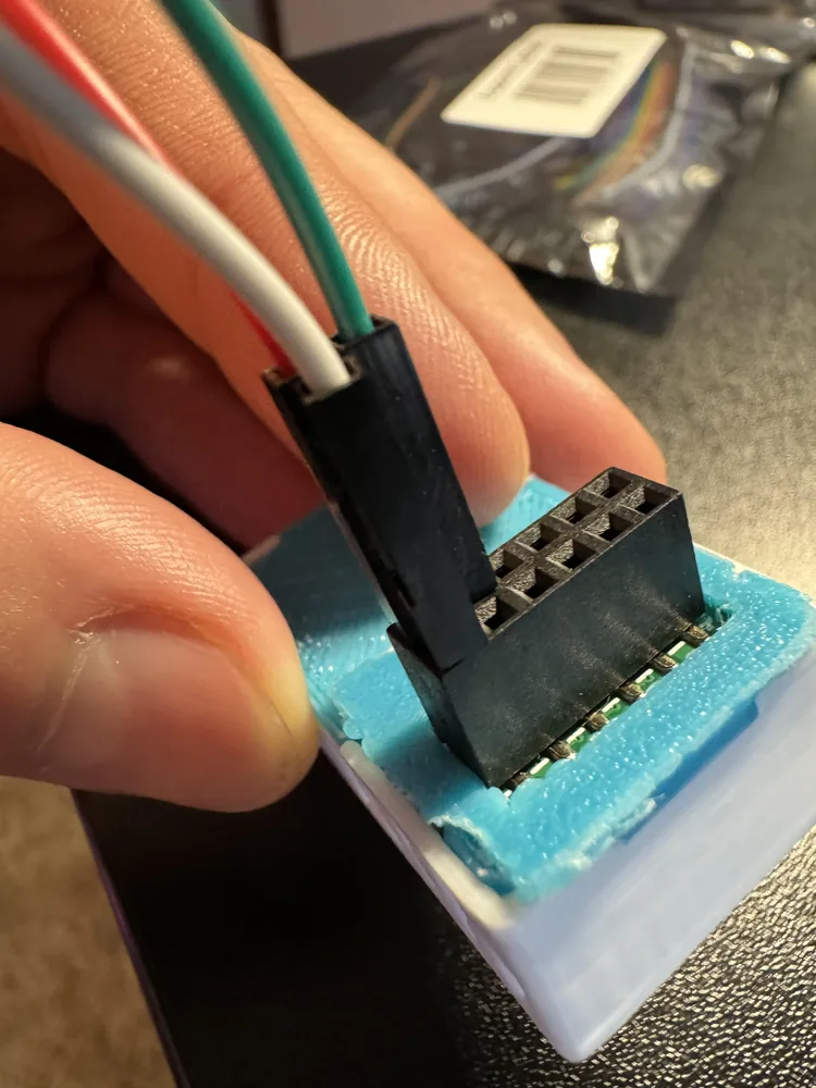
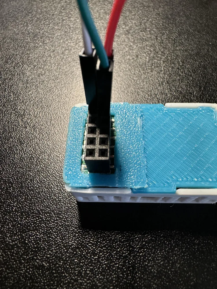
-
Plug the other end into the strip. Most strips come with a JST-SM pigtail carrying the same three colors, so the wires match up directly. The connector is rated to 3A.
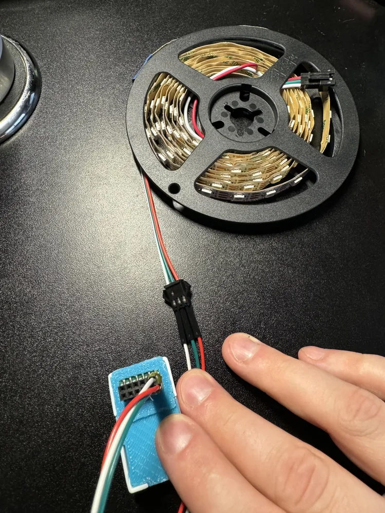
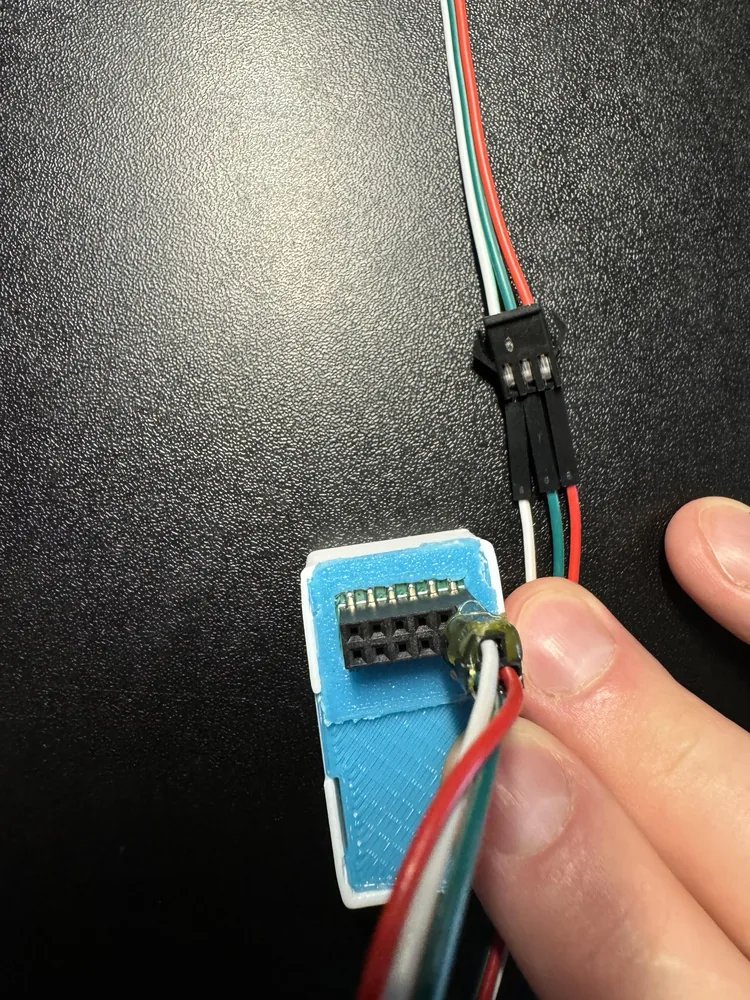
-
Check the direction before you power anything on. Arrows printed along the strip show which way data flows, and they need to point away from the AIR-1.
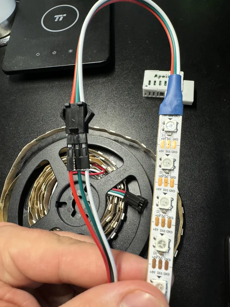
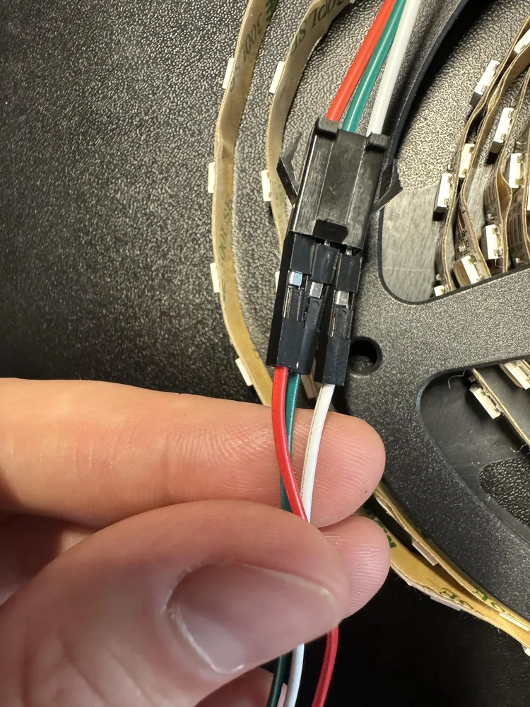
A dab of hot glue across the outer shells of the three DuPont connectors stiffens them into a single plug. (1)
- Keep glue out of the header's female pins. It will ruin the addon.
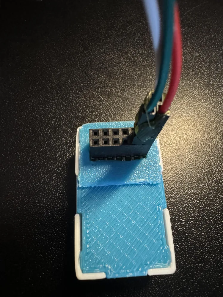
Adding the strip to your YAML
The AIR-1 knows nothing about the strip until you tell it how many LEDs there are and which pin they sit on.
-
Open the ESPHome Device Builder app, find your AIR-1, and click Edit.
-
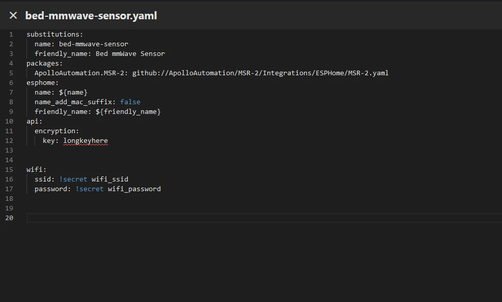
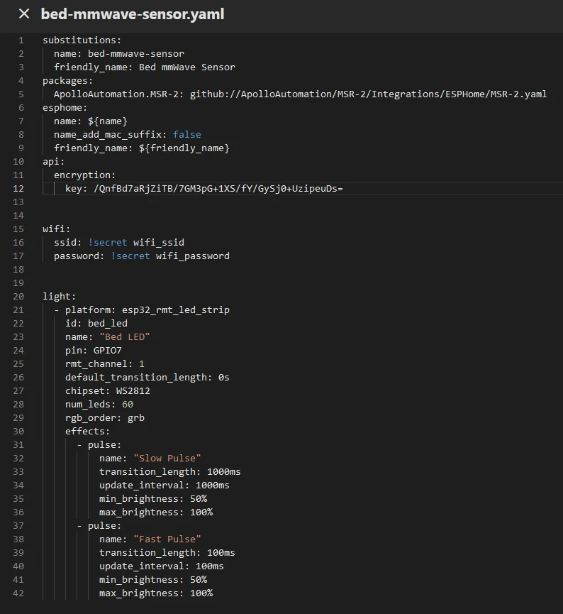
Add the block below at the bottom of the file, flush with the left margin so
light:lines up withpackages:andwifi:. Setnum_ledsto the number of LEDs on your strip, and changepinif you wired to a different port.light: - platform: esp32_rmt_led_strip id: bed_led name: "Bed LED" pin: GPIO7 chipset: WS2812 channel_colors: GRB num_leds: 60 default_transition_length: 0s effects: - pulse: name: "Slow Pulse" transition_length: 1000ms update_interval: 1000ms min_brightness: 50% max_brightness: 100% - pulse: name: "Fast Pulse" transition_length: 100ms update_interval: 100ms min_brightness: 50% max_brightness: 100% - addressable_rainbow: -
Check that the editor shows no red error markers.
-
Click Save, then Install, and pick Wirelessly. ESPHome compiles the firmware and sends it to the AIR-1. The first build takes a few minutes.
Older versions of this guide set rmt_channel: 1 on the light. ESPHome dropped that option, and leaving it in now fails validation, so the block above does not use it.
The ESPHome light effects reference covers everything else you can add under effects:, including addressable_scan.
Controlling it from Home Assistant
Once the install finishes, the AIR-1 exposes a new light entity called Bed LED.
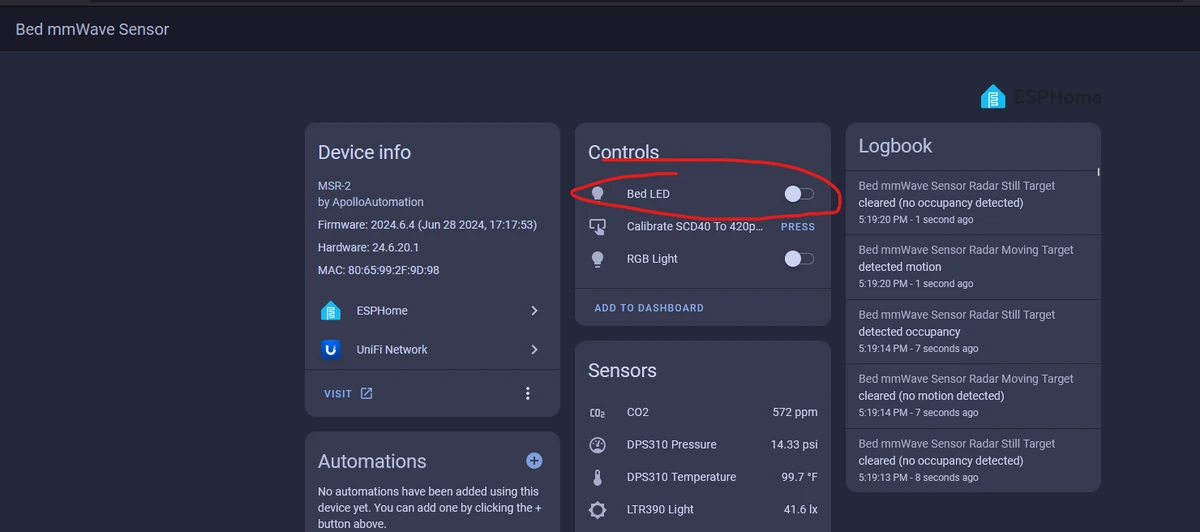
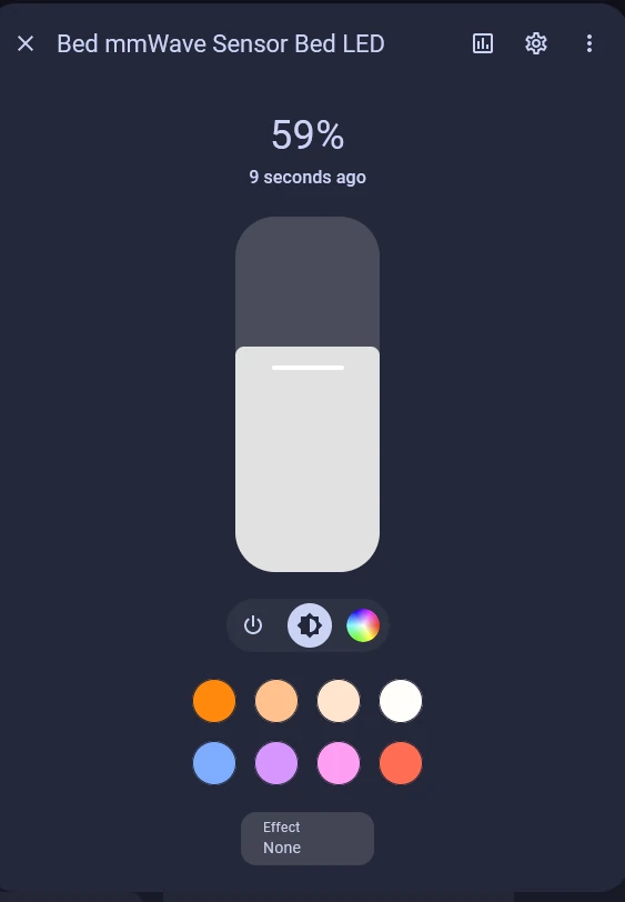
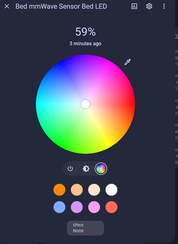
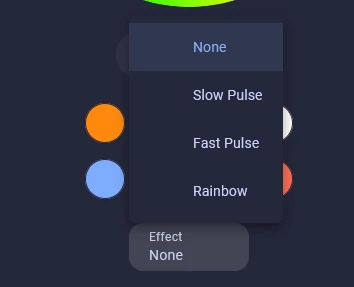
Click the entity name to open the light card. The color wheel covers the full range, and the effects list holds the two pulses and the rainbow from the YAML above.
That's all folks! Thanks to Smart Home Sellout for putting this tutorial together.