MSR-2
mmWave CO2 Multisensor
- Setup
- Getting Started
- Sensor Definitions
- Bluetooth Tracking with MSR-2
- General Tips
- How To Change The Update Frequency Of Sensors
- Calibrating And Updating
- Updating MSR-2 Firmware
- How To Tune mmWave Using Home Assistant
- How To Tune mmWave Using HLKRadarTool
- MSR-2 Temperature & Humidity Offsets
- CO2 Calibration For MSR-2
- Examples
- MSR-2 Home Assistant Dashboard Examples
- Using MSR-2 Buzzer
- How To Use The Apollo GPIO Header To Control An LED Strip
- MSR-2 Automation Guide
- MSR-2 Examples From GitHub
- MSR-2 + Alarmo Home Security Install
- Additional Info
- Troubleshooting
- Manually Uploading Code Through ESPHome
- Putting The MSR-2 In Boot Mode
- Teardown and Reassembly of the MSR-2
- MSR-2 Reviews
Setup
Getting Started
Please refer to the general getting started article
Sensor Definitions
Once added to Home Assistant you can configure different settings for your sensor. Below is what each setting does.
Controls
- RGB Light
- A RGB Neopixel. Click on the light bulb to change the color. Click on the toggle to turn on or off
Sensors
- CO2
- True CO2 reading from the SCD40. This will be Unknown if you do not have the CO2 module. This can be calibrated following this guide but does come precalibrated: Here
- ESP Temperature
- This is the temperature of the internal ESP chip. Think of it like your measured CPU temp on your PC
- LTR390 Light
- Light level measured in lux by LTR390
- LTR390 UV Index
- UV index measured by LTR390
- Radar Detection Distance
- The last detected distance by the radar. This will stay at the last known value so sometimes can be misleading
- Radar Move Energy
- The amount of movement measured by the LD2410B. Faster movements have higher %
- Radar Moving Target
- Does the radar have a moving target it is tracking
- Radar Still Distance
- The last measured distance of a still target. It will hold the last value so sometimes can be misleading
- Radar Still Energy
- The energy of the current still target
- Radar Still Target
- Does the radar have a still target
- Radar Target
- Does the radar have a still or moving target. Good for triggering automation.
- Radar Zone 1 Occupancy
- This is a configurable zone. Think of zones like distances from the radar unit. Zone 1 might be from 0 cm to 120 cm from the sensor. This is telling you if there is someone in that zone. The zones can be defined in the configuration section with “Radar End Zone 1”
- Radar Zone 2 Occupancy
- Same as zone 1 but just the second zone from the sensor
- Radar Zone 3 Occupancy
- Same as zone 1 & 2 but with the third zone.
- Same as zone 1 & 2 but with the third zone.
Configuration
- CO2 Calibration Number
- See calibrating CO2: Here
- ESP Reboot
- Performs a restart of the sensor
- Factory Reset Radar
- Sets the radar's move thresholds back to their original values from the manufacturer
- g0-g8 Move & Still Threshold
- Please refer to the radar tuning guide: Here
- Radar Control Bluetooth
- This allows you to turn on the LD2410's Bluetooth. This allows you to connect to the HLK Radar phone app if you wanted to upload new firmware to the radar unit (Not the MSR-1 in general, just the radar chip)
- Radar Distance Resolution
- Best to keep on 0.75m in many cases. If you change it to 0.25m the first few gates become very very sensitive and the maximum detection distance shrinks a lot.
- Radar Zone 1 Start
-
This sets the starting distance for Zone 1 in cm. This is the distance from the sensor to the start of Zone 1
-
- Radar End Zone 1
- This defines “Zone 1” of the radar. It is a distance from the sensor that specifies what “Zone 1” is. It connects to the “Radar Zone 1 Occupancy” sensor. So if this number is set to “10” that means from 0 to 10 centimeters from the sensor is zone 1.
- Radar End Zone 2
- Same as Zone 1. This defines where zone 2 ends
- Radar End Zone 3
- Like Zone 2, this defines where zone 3 ends
- Radar Max Move Distance
- Maximum distance gate for movement detection. Value between 2 and 8 inclusive
- Useful in a bathroom or other scenario where you want to avoid detection after a certain gate count.
- Useful for triggering on "radar target" instead of triggering on zone 1/2/3 occupancy instead.
- Radar Max Still Distance
- Maximum distance gate for still detection. Value between 2 and 8 inclusive. Defaults to 8.
- Useful in a bathroom or other scenario where you want to avoid detection after a certain gate count.
- Useful for triggering on "radar target" instead of triggering on zone 1/2/3 occupancy instead.
- Radar Timeout
- The time in seconds that the radar's presence will stay high after the target is lost.
- The time in seconds that the radar's presence will stay high after the target is lost.
Bluetooth Tracking with MSR-2
Please refer to the general Bluetooth tracking article
General Tips
MSR-2


Light Sensor (LTR-390UV)

- When mounting the MSR-2 be sure to position the device so that the two large holes are not covered
- This allows more light to enter and will ensure better accuracy
- The onboard RGB LED will trigger the light sensor
- Be cognizant of this when making automations based on light/LUX
Mounting


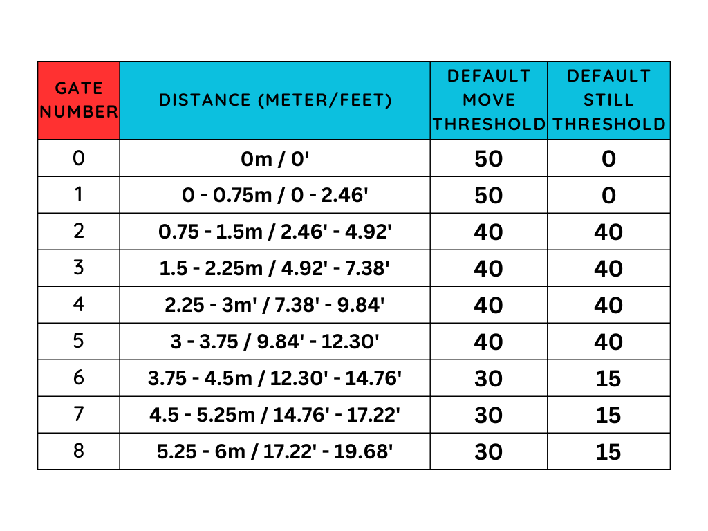
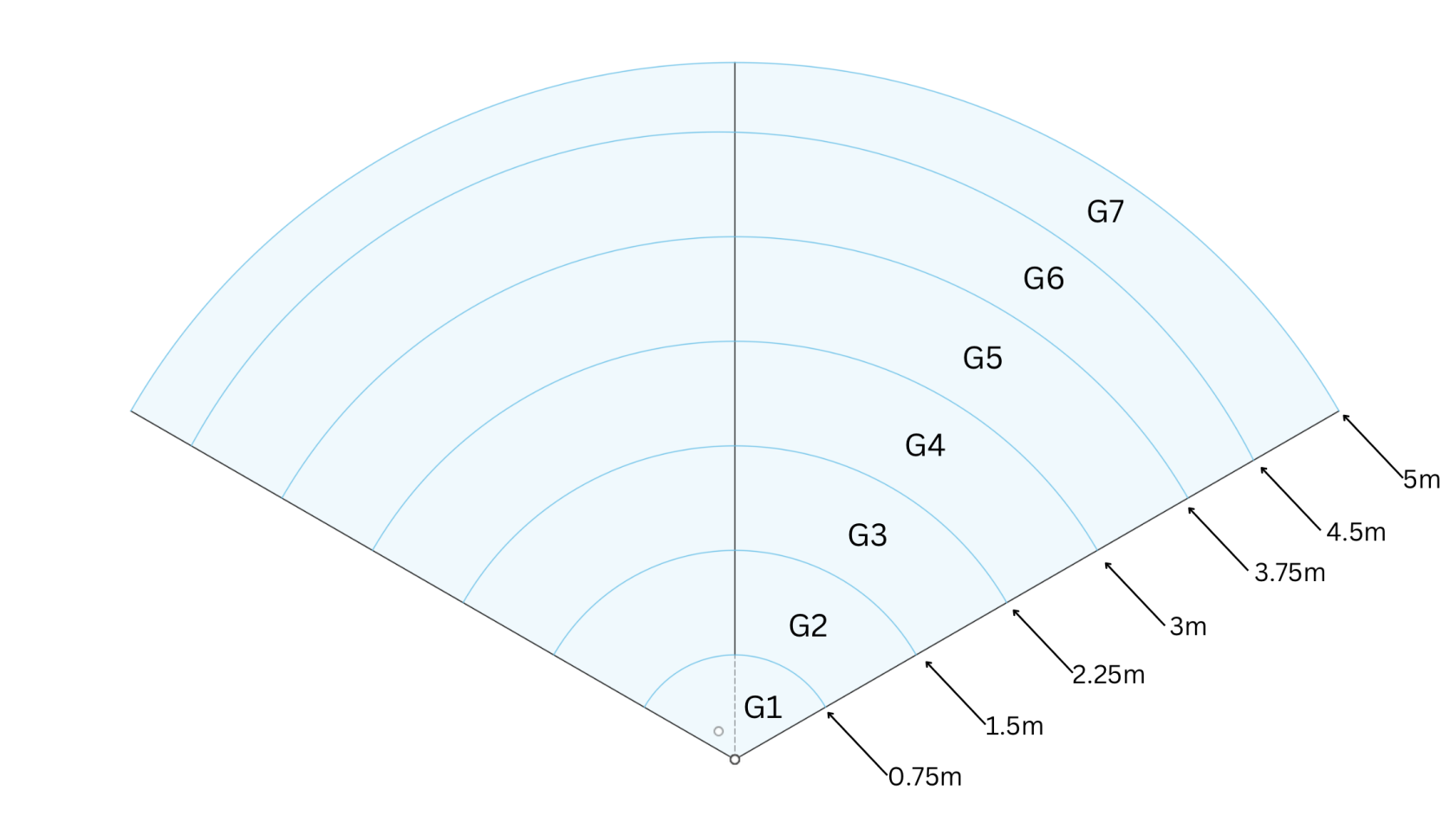
Gate and FOV Visualization


- FOV angle -60 to 60
- Gate images above are using a Radar Distance Resolution of 0.75m
-
Gates are pre-defined by the radar module and are in meters (m)
-
Zones are user-configurable and are in centimeters (cm)


Increased ESP Temperature
If you are experiencing higher than normal ESP temperatures ~140+ degrees F then changing the wifi power save mode option might help decrease the temperature. Here is the link to the ESPHome WiFi Component Power Save Mode.
Power Save Mode
The WiFi interface of all ESPs offer three power save modes to reduce the amount of power spent on WiFi. While some options can reduce the power usage of the ESP, they generally also decrease the reliability of the WiFi connection, with frequent disconnections from the router in the highest power saving mode.
NONE (least power saving, Default for ESP8266)
LIGHT (Default for ESP32)
HIGH (most power saving)
wifi:
  # ...
  power_save_mode: none
The code above can be added to the devices .yaml through the ESPHome addon edit button.
(Thank you for the suggestion, Brian!)
(Referenced from ESPHome website)
How To Change The Update Frequency Of Sensors
How To Change The Update Frequency Of Sensors
Calibrating And Updating
Updating MSR-2 Firmware
Please refer to the general firmware update article
How To Tune mmWave Using Home Assistant
If you're experiencing false triggers, we recommend using Radar Engineering Mode (REM) to monitor the gate energy and adjust the gate threshold to eliminate them.
Here is a quick introduction video of the ld2410b gates and zones.
Here is a video of how to tune the mmWave sensor using radar engineering mode,
- Open Home Assistant
- Navigate to Settings>Devices & services>ESPHome>Select the MSR-2
- Scroll down to the Configuration section
- Turn on Radar Engineering Mode (REM)
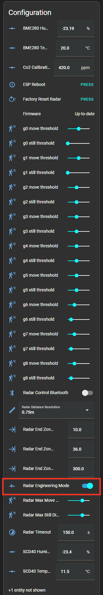
- Scroll down to the Diagnostic section and you will see that REM shows the move and still energy for gates 0-8
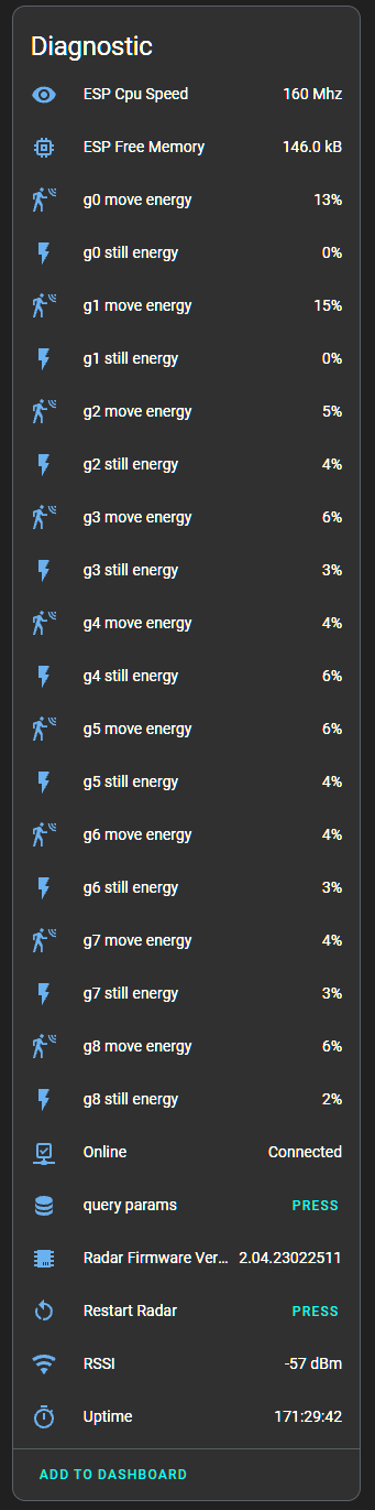
- The gates are different distances from the sensor
- Moving the gate still and move threshold slider to the right increases the amount of energy needed to trigger the sensor. Do this if you want the gate to be less sensitive.

- Moving the gate still and move threshold slider to the left decreases the amount of energy needed to trigger the sensor. Do this if you want the gate to be more sensitive.


Alternate Method
Thanks to MakeItWorkTech for this method!
"I ended up maxing out the sliders on all gates and then bringing them down just enough to pick up human presence. Definitely easier than using the LD2410B app."
Example
- You may have an open-concept kitchen and living room, and you want the MSR-1 to activate your under-cabinet lights only when you're in the kitchen.
Here's how:
- Stand in the desired trigger locations.
- Observe the gate energy.
- Adjust the gate threshold slider to the right, increasing the energy required to trigger the mmWave sensor. This ensures that your kitchen lights only come on when you're actually in the kitchen, not just walking by in the living room. Also, you can lower the gate threshold in the kitchen by moving the slider to the left. This makes the mmWave sensor more sensitive, even when standing still. This way, you avoid having the lights go off while reading a recipe or doing the dishes.
- From clarinetJWD, "Engineering mode is what I was missing at first. I did exactly that, and now detection is basically perfect! My under cabinet lights now come on to max brightness whenever someone is in the kitchen, and return to their previous value when they leave. Next up is replacing the really flaky motion switch in my garage so it stops shutting off when I'm doing a project at the workbench! Thanks, these are really good.
References
- https://youtu.be/dAzHXpP3FcI?t=431
- https://community.home-assistant.io/t/ld2410-esphome-tips/477058/316
- https://www.youtube.com/watch?v=l212Lvo1R6s
How To Tune mmWave Using HLKRadarTool
Auto-Calibration (Average, Maximum, and Intelligent)
1. Download the HLKRadarTool app for either Android or Apple
- The default password to connect to the HLKRadarTool is HiLink
2. Ensure the mmWave radar you want to tune has Radar Control Bluetooth turned on. Home Assistant > Settings > Devices & services > ESPHome Devices > Select Device > Scroll down and toggle on Radar Control Bluetooth
3. Open the app and select your device
4. Turn on Engineering Mode
5. Select More and then select Parameter settings
6. Select Detect background noise
7. Insert Delay detection and Detection time values. (For iPhone users Delay detection cannot be 0). Then select Start. This will give us our reference values so we can auto-calibrate the mmWave sensor.
8. Select Back to navigate to the Parameter settings. Then select one of the auto-calibration buttons.
Average
- Sets the gate sensitivity to the average move and still energy
Maximum
- Sets the gate sensitivity to the maximum move and still energy
Intelligent
- Sets the gate sensitivity equal to or just above the maximum move and still energy
9. Now your mmWave should be tuned to your environment!
Manual Calibration
1. Follow steps 1-5 above
2. Select Motion or Static sensitivity, change it to your desired value, and select Set
3. Now your mmWave should be tuned to your environment!
MSR-2 Temperature & Humidity Offsets
Simple Offsets for Temperature and Humidity:
Please add these to the bottom of your esphome yaml for your device then click save and install. Once you are finished, you will have two new boxes inside the home assistant esphome integration device page for your device where you can fill in an offset. Give them up to 1minute to take effect!
sensor:
  - id: !extend scd40
    humidity:
      name: "Humidity"
      id: "humidity"
      filters:
        - lambda: return x - id(scd40_humidity_offset).state;
    temperature:
      name: "Temperature"
      id: "temperature"
      filters:
        - lambda: return x - id(scd40_temperature_offset).state;
number:
  - platform: template
    name: SCD40 Humidity Offset
    id: scd40_humidity_offset
    restore_value: true
    initial_value: -18.86
    min_value: -70.0
    max_value: 70.0
    entity_category: "CONFIG"
    unit_of_measurement: "%"
    optimistic: true
    update_interval: never
    step: 0.1
    mode: box
  - platform: template
    name: SCD40 Temperature Offset
    id: scd40_temperature_offset
    initial_value: 14.54
    min_value: -70.0
    max_value: 70.0
    entity_category: "CONFIG"
    unit_of_measurement: "°C"
    optimistic: true
    update_interval: never
    step: 0.1
    mode: box
DPS310 & SCD40 Sensors: Overcoming Temperature & Humidity Reading Challenges
The DPS310 and SCD40 sensors are known for their precision in measuring temperature and humidity. However, like all sensor systems, they can sometimes provide inaccurate readings due to various factors. In the case of the DPS310 and SCD40 sensors, one significant challenge arises from the heat produced by the ESP chip, which can alter the environment inside its enclosure, thereby skewing the readings.
Adjusting the DPS310 and SCD40 Temperature Offset
For users who want to fine-tune their sensors, the DPS310 and SCD40 Temperature Offset entities can be manually adjusted to match the conditions in their home. The offset values are subtracted from the raw temperature & humidity readings in the firmware to update the sensor readings in the home assistant entity. For example: scd40_temperature entity = raw scd40 temperature reading - scd40_offset.
By default, these offsets are preset to values based on our NIST certified thermometer, it's important to note that these values are calibrated for our environment. They might not be accurate for all settings. Therefore, by using a reference thermometer, users can adjust the difference between the readings to get a more accurate representation.
Users will also notice the dps310_temperature_calibrated, scd40_humidity_calibrated, and scd40_temperature_calibratedentities. These values utilize the linear filter in the ESPHome firmware to adjust the readings based on our collected data. Again, due to environmental differences, these might not always be precise.
Modeling the Relationship Between Sensors
Another approach to getting accurate readings is to model the relationship between the ESP temperature and the other sensors compared against a reference temperature. This can be achieved by creating a template sensor in Home Assistant that employs a decision tree or our regression coefficients.
Here's an example that can be added to a configuration YAML:
sensor:
  - platform: template
    sensors:
      estimated_reference_temperature:
        friendly_name: "Estimated Temperature"
        unit_of_measurement: '°C'
        value_template: >
          {{
            0.3228 * states('sensor.apollo_msr_1_a79e24_esp_temperature') | float +
            0.8702 * states('sensor.apollo_msr_1_a79e24_scd40_temperature') | float +
            -0.1285 * states('sensor.apollo_msr_1_a79e24_dps310_temperature') | float +
            -0.0491 * states('sensor.apollo_msr_1_a79e24_scd40_humidity') | float +
            0.0851
          }}


      estimated_reference_humidity:
        friendly_name: "Estimated Humidity"
        unit_of_measurement: '%'
        value_template: >
          {{
            -1.2468 * states('sensor.apollo_msr_1_a79e24_esp_temperature') | float +
            -2.1959 * states('sensor.apollo_msr_1_a79e24_scd40_temperature') | float +
            2.9604 * states('sensor.apollo_msr_1_a79e24_dps310_temperature') | float +
            0.2380 * states('sensor.apollo_msr_1_a79e24_scd40_humidity') | float +
            1.8283
          }}
For users who want to gather their own data with a reference sensor and MSR-2 within their home, we recommend logging data to a CSV using the following YAML entries:
#Configuration.yaml
notify:
  - platform: file
    name: sensor_csv_log
    filename: /config/sensor_log.csv
    timestamp: False

#Automations.yaml
  - id: log_sensor_data_to_csv
    alias: "Log Sensor Data to CSV"
    trigger:
      platform: time_pattern
      minutes: "/1"  # Log data every minute to match reference sensor
    action:
      - service: notify.sensor_csv_log
        data_template:
          message: >
            {{ now().strftime('%Y-%m-%d %H:%M:%S') }},
            {{ states('sensor.apollo_msr_1_a79e24_esp_temperature') | default('NA') }},
            {{ states('sensor.apollo_msr_1_a79e24_scd40_temperature') | default('NA') }},
            {{ states('sensor.apollo_msr_1_a79e24_dps310_temperature') | default('NA') }},
            {{ states('sensor.apollo_msr_1_a79e24_scd40_humidity') | default('NA') }},
            {{ states('number.apollo_msr_1_a79e24_dps310_temperature_offset') | default('NA') }},
            {{ states('number.apollo_msr_1_a79e24_scd40_humidity_offset') | default('NA') }},
            {{ states('number.apollo_msr_1_a79e24_scd40_temperature_offset') | default('NA') }},
            {{ states('sensor.apollo_msr_1_a79e24_uptime') | default('NA') }}
The Interrelation of Temperature and Humidity
It's important to understand that temperature and humidity share an interdependent relationship. When the air temperature rises, its capacity to hold moisture increases, which can decrease relative humidity levels. Conversely, when the temperature falls, the air's capacity to hold moisture decreases, leading to increased humidity. This relationship plays a significant role in how sensors detect and interpret readings, making it even more crucial to ensure accuracy.
Advanced Accuracy with GPIO
For those seeking the highest accuracy, an advanced solution is available. The exposed mezzanine connector on the back of our Apollo boards can be utilized to connect a temperature/humidity sensor. This modification can dramatically improve both temperature and humidity readings, providing data that's as accurate as possible.
CO2 Calibration For MSR-2
Please refer to the General CO2 Calibration article
Examples
MSR-2 Home Assistant Dashboard Examples
Radar Scatter Plot With Apex Charts For MSR-2

type: custom:apexcharts-card
header:
  show: true
  title: MSR-1 Radar Distance
  show_states: true
  colorize_states: true
apex_config:
  legend:
    position: top
    horizontalAlign: center
    offsetX: -80
    offsetY: 0
experimental:
  brush: true
brush:
  selection_span: 4h
graph_span: 24hr
chart_type: scatter
series:
  - entity: sensor.apollo_msr_1_a79e14_radar_detection_distance
    name: Detection
    stroke_width: 1
    color: green
    show:
      in_brush: true
      extremas: true
  - entity: sensor.apollo_msr_1_a79e14_radar_moving_distance
    name: Moving
    stroke_width: 1
  - entity: sensor.apollo_msr_1_a79e14_radar_still_distance
    name: Still
    stroke_width: 1
CO2 Charts
Home Assistant Sensor

graph: line
type: sensor
entity: sensor.apollo_msr_1_a79e38_co2
detail: 2
name: Bedroom CO2
hours_to_show: 24
Custom: Plotly Graph Card

type: custom:plotly-graph
entities:
  - entity: sensor.apollo_msr_1_a79e38_co2
hours_to_show: 24
refresh_interval: 10
title: Bedroom CO2
Home Assistant Guage

type: gauge
entity: sensor.apollo_msr_1_a79e38_co2
needle: true
unit: ppm
min: 0
max: 3000
severity:
  green: 0
  yellow: 1000
red: 2000Using MSR-2 Buzzer
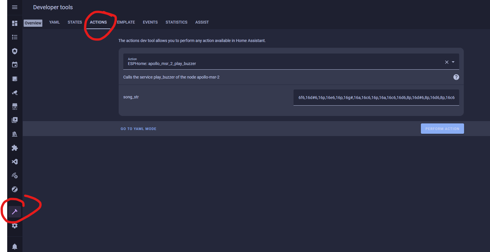
This guide will walk you through using the buzzer on your MSR-2. You can also use the "action" in an automation in Home Assistant.
- Open Home Assistant and navigate to developer tools in the bottom left

2. Click on services
3. Choose your MSR-2's buzzer (You can type in buzzer to find it easier)
4. Put a rtttl tone into the the string box
-
- Mario:
smb:d=4,o=5,b=100:16e6,16e6,32p,8e6,16c6,8e6,8g6,8p,8g,8p,8c6,16p,8g,16p,8e,16p,8a,8b,16a#,8a,16g.,16e6,16g6,8a6,16f6,8g6,8e6,16c6,16d6,8b,16p,8c6,16p,8g,16p,8e,16p,8a,8b,16a#,8a,16g.,16e6,16g6,8a6,16f6,8g6,8e6,16c6,16d6,8b,8p,16g6,16f#6,16f6,16d#6,16p,16e6,16p,16g#,16a,16c6,16p,16a,16c6,16d6,8p,16g6,16f#6,16f6,16d#6,16p,16e6,16p,16c7,16p,16c7,16c7,p,16g6,16f#6,16f6,16d#6,16p,16e6,16p,16g#,16a,16c6,16p,16a,16c6,16d6,8p,16d#6,8p,16d6,8p,16c6 - Cantina:
Cantina:d=4,o=5,b=250:8a,8p,8d6,8p,8a,8p,8d6,8p,8a,8d6,8p,8a,8p,8g#,a,8a,8g#,8a,g,8f#,8g,8f#,f.,8d.,16p,p.,8a,8p,8d6,8p,8a,8p,8d6,8p,8a,8d6,8p,8a,8p,8g#,8a,8p,8g,8p,g.,8f#,8g,8p,8c6,a#,a,g - Star Wars Imperial Death March:
StarWars/Imp:d=4,o=5,b=112:8d.,16p,8d.,16p,8d.,16p,8a#4,16p,16f,8d.,16p,8a#4,16p,16f,d.,8p,8a.,16p,8a.,16p,8a.,16p,8a#,16p,16f,8c#.,16p,8a#4,16p,16f,d.,8p,8d.6,16p,8d,16p,16d,8d6,8p,8c#6,16p,16c6,16b,16a#,8b,8p,16d#,16p,8g#,8p,8g,16p,16f#,16f,16e,8f,8p,16a#4,16p,2c# - Huge list: https://picaxe.com/rtttl-ringtones-for-tune-command/
- This is a good site to test rttl tones: https://adamonsoon.github.io/rtttl-play/
- Mario:
5. Click on the ACTIONS button in bottom right
How To Use The Apollo GPIO Header To Control An LED Strip
This tutorial will guide you through setting up one of our MSR-2 devices (works with any mezzanine port on any Apollo Device) with the optional $4.99 GPIO Header which adds pins for you to easily add functionality to your device! In this tutorial, however, we will be focusing on adding an LED strip to your Apollo device.
Materials Needed for tutorial:
- Apollo MSR-2, Apollo MTR-1, and all other future Apollo Automation products with the mezzanine port.
- Apollo GPIO Header
- ws2812b aka neopixel RGB led strip or similar. sk6812 RGBW strip will also work.
- Optional DuPont Cables for GPIO Header but any DuPont cables will do.
- USB-C cable and power brick to power MSR-2
You are limited to 300mA of power output from the 5v port. You can either attach an external power supply and power the MSR-2 via 5v and gnd pins or work with the limited power output of the port

Above is an image of the GPIO Header and its pinouts. We can use ports 2,4,6,7 for our data channel to an LED strip or multiple LED strips. We will also use the top two ports which are ground and 5v for power.
Did you know you can power the esp32 from the 5v and gnd pin? That means you can connect an external power supply and power it without the side USB port being used! This also allows for more power to be given to your LEDs!
We cannot use the IO ports 0,1,18, or 19 for LEDs but you can use ports 0 and 1 for i2c sensors.
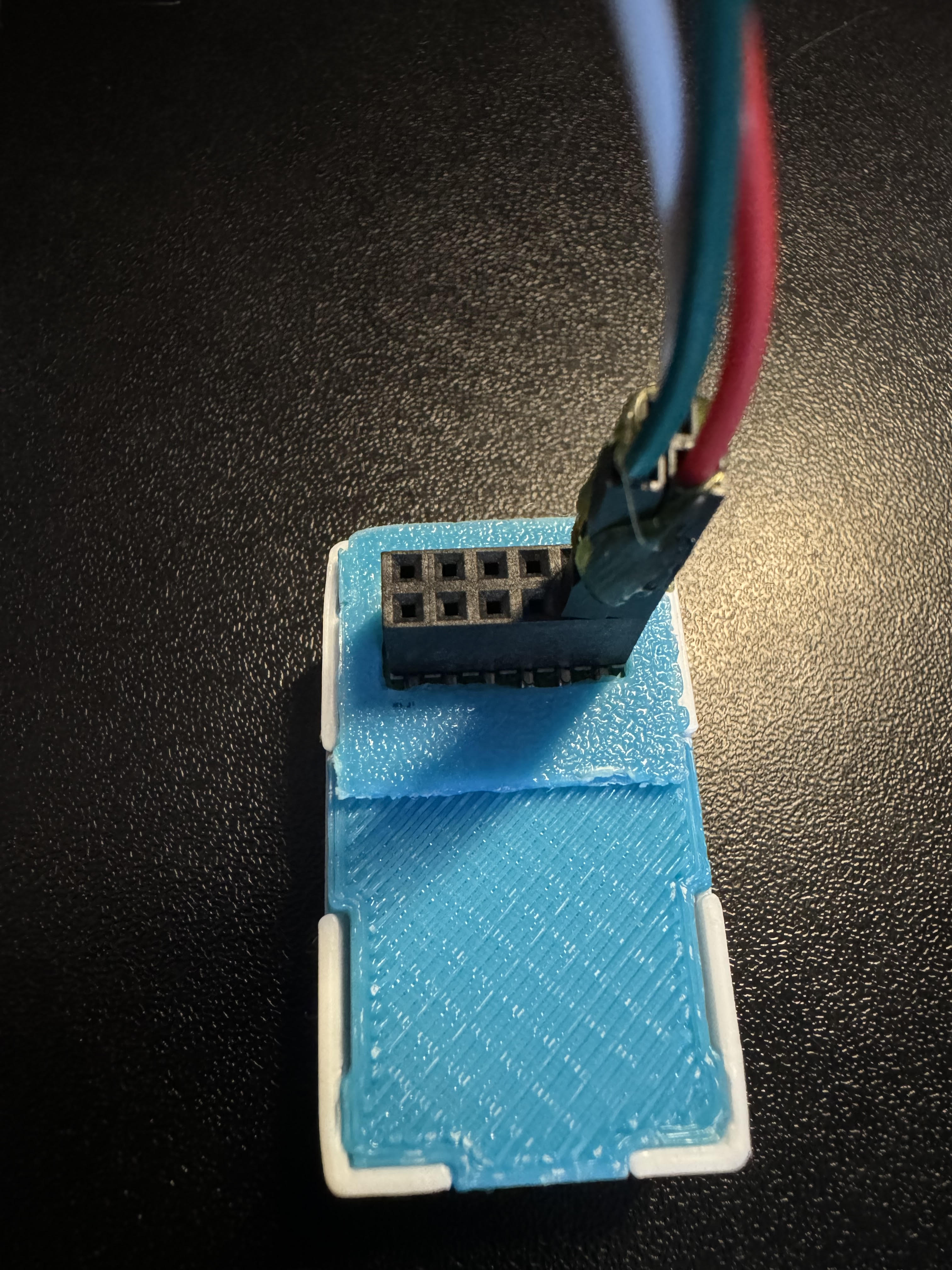
Connecting the GPIO Header to the MSR-2
The first thing we will do is remove our MSR-2 back plate and connect our GPIO Header to our MSR-2 and then put the new GPIO back plate on (blue).
Step 1. Remove the backplate of the MSR-2


Step 2. Line up the Xs shown on the msr-2 and the GPIO Header. They should both be facing in the same direction as shown below.

Step 3. Gently push down onto the GPIO Header as shown below:

Step 4. Confirm the GPIO Header is seated properly as shown below.

Step 5. Slide the GPIO Header back plate for the MSR-2 over your sensor and gently push down until it clicks into place.

If the back plate does not gently go onto the sensor please investigate and confirm it is in the right orientation.
Connecting DuPont pins to proper GPIO ports
Now we need to reference the GPIO pinout we looked at above and then connect three wires. You will need three male-to-male DuPont wires included in your kit. I suggest using red for power aka 5v, White for ground aka GND, and green for data aka port IO7. Most LED strips will also have this same color scheme and it's easier to match like colors together.


You can add a bit of hot glue to the Dupont wires to hold them together. DO NOT put hot glue into the GPIO Header's female pins that will ruin the addon. I am only suggesting that you can hot-glue the Dupont pins outer shell themselves together to stiffen them up.
Connecting DuPont pins to LED Strip
Next, we need to connect the other side of the Dupont pins to the LED strip. Most likely your LED strip will have a JST-SM connector which is a 3amp max connector with three wires connected: red for 5v, green for data, and white for gnd. We will be matching up our red, green, and white wires already attached to the GPIO add-on pins in the MSR-2 (using IO7 as the data pin for this tutorial)


Make sure to connect to the correct side of the LED strip. The led strip will have an arrow going down the led strip showing one direction for the data line. you want the data channel going FROM the msr-2 TO the led strip going in a "forward" direction as shown below.


Edit the YAML of your MSR-2 to let it know about your new LED strip
Finally, we need to tell the MSR-2 that we connected an LED strip. We need to tell it how many LEDs we have and we need to tell it that it's our second LED since the built-in LED is the first. This tutorial assumes you are comfortable with the ESPHome dashboard.
Step 1. Open ESPhome Dashboard and click edit to bring up the yaml your sensor is currently using.

You will see some YAML code here and you do NOT want to touch anything above line 20. If you need to, click your cursor at the end of wifi_password and hit enter to create a new line then make sure you backspace until you are "flush" with the line numbers like how wifi: is.
Step 2. Copy the code below and paste it to line 20 in your ESPHome yaml for this device.
light:
  - platform: esp32_rmt_led_strip
    id: bed_led
    name: "Bed LED"
    pin: GPIO7
    rmt_channel: 1
    default_transition_length: 0s
    chipset: WS2812
    num_leds: 60
    rgb_order: grb
    effects:
      - pulse:
          name: "Slow Pulse"
          transition_length: 1000ms
          update_interval: 1000ms
          min_brightness: 50%
          max_brightness: 100%
      - pulse:
          name: "Fast Pulse"
          transition_length: 100ms
          update_interval: 100ms
          min_brightness: 50%
          max_brightness: 100%
      - addressable_rainbow:

You change the rmt_channel to 1 because 0 is being used by the built-in LED of the MSR-2.
Step 5. Go into home assistant and confirm you now have a new light entity called Bed LED

Step 6. Click on the name "Bed LED" circled and it will pop up a color picker. You can then choose the color wheel option to pick any color of the rainbow, or select "effect" and choose an effect.


That's all folks! Thanks to Smart Home Sellout for putting this tutorial together!
MSR-2 Automation Guide
MSR-2 Examples From GitHub
MSR-2 Examples from GitHub
MSR-2 + Alarmo Home Security Install
My grandmother wanted a security system that would alert her when there was movement in her home after she had gone to bed. So, I set up three of our Apollo Automation mmWave sensors. These devices, plus the Alarmo add-on, quickly and easily allowed me to install a fully local, private, cloud-free, and no monthly subscription security system. She can arm/disarm it with one button on her Home Assistant dashboard, and it makes her feel much safer. This guide assumes you already have a motion/presence sensor installed on HA.
1. Install HACS
2. Install Alarmo and the Alarmo Card (Pretty Arm and Disarm card for your HA dashboard)
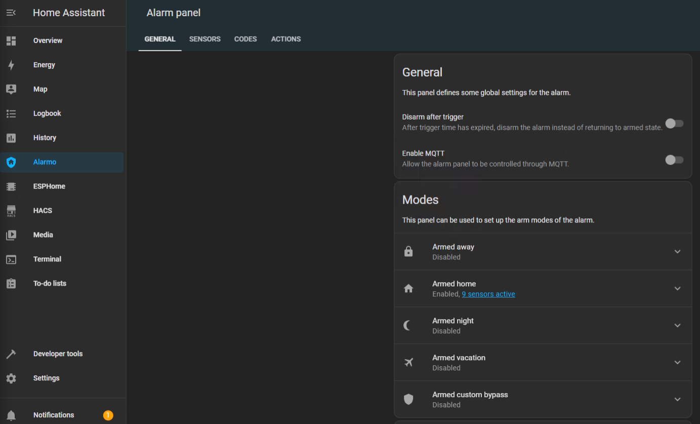
3. Find Alarmo on the left, select the Sensors tab, and toggle on the sensor entities that you would like to use for your alarm system.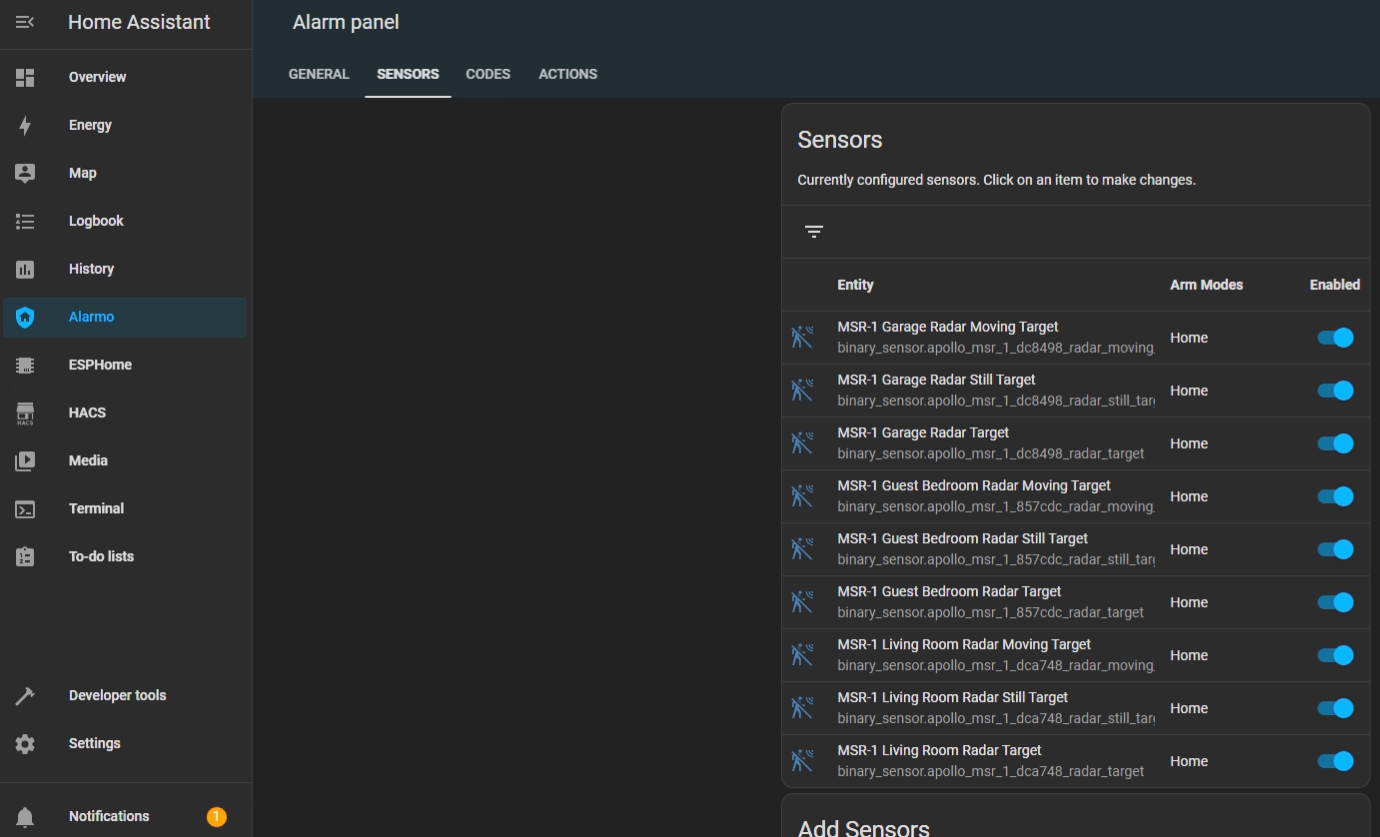
4. Now select the Actions tab and under Condition > Event > Select "Alarm is triggered". You can also select the device you would like to receive a notification on under Task > Target > Select Device (Phone, tablet, etc.)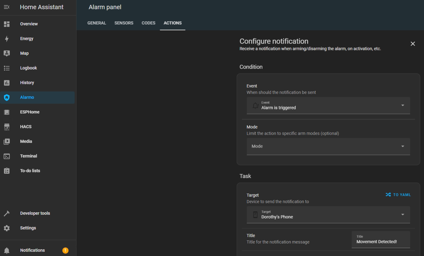
5. You can change the Title, Message, and Name of the alarm notification.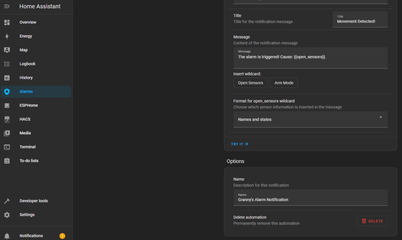
6. After saving that action we can add another one that will turn on our sensor lights and/or make the onboard piezo buzzers play an alarm sound. Uner Entity select your sensors RGB light.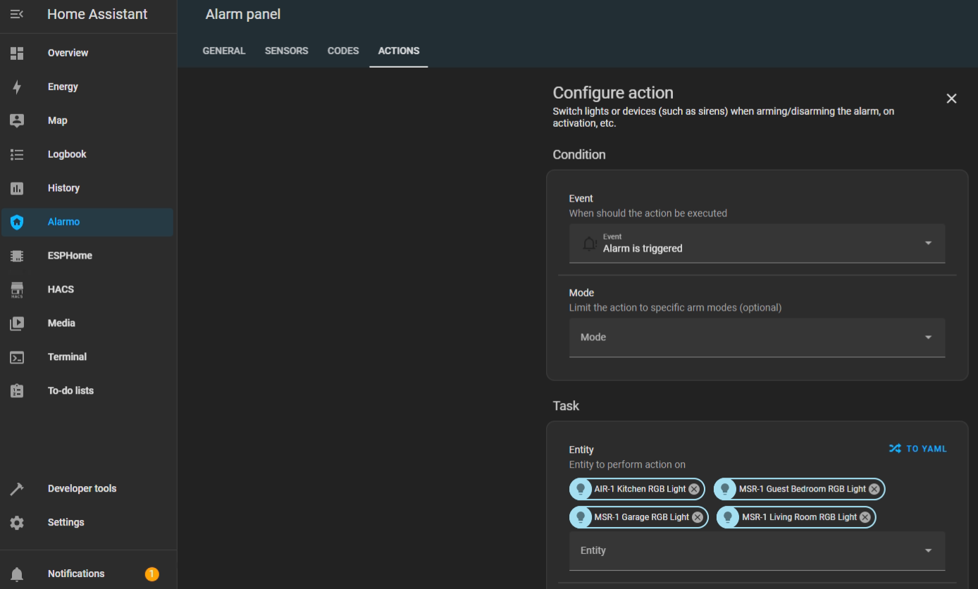
7. Under Action select Turn On and now your sensors RGB lights will turn on when the alarm is triggered.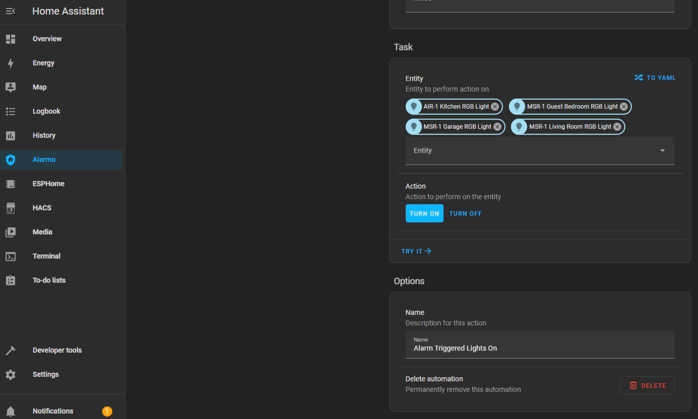
8. And that's it, seriously... Now you can enjoy a free and local security system.
We hope this was helpful and please let us know if there are any questions!
Additional Info
mmWave Presence Sensor Comparison
| Column1 | Apollo MSR-1 | Apollo MSR-2 | Everything Presence One Kit | Everything Presence Lite Kit | Screek Human Sensor 1U | Screek Human Sensor 2A | Aqara FP1 | Aqara FP2 | Apollo MTR-1 |
| Price (USD) | $ 34.99 | $ 34.99 | $ 78.00 | $ 37.00 | $ 25.99 | $ 29.99 | $ 49.99 | $ 82.99 | $ 36.99 |
| Motion Detection | |||||||||
| mmWave | LD2410B | LD2410B | SEN0395 | LD2450 | LD2410C | LD2450 | BGT60TR13C | IWR6843 | LD2450 |
| Detection Distance (m) | 6 | 6 | 9 | 6 | 6 | 6 | 5 | 6 to 8 | 6 |
| Detection Zones | 3 zones and 9 gates (adjustable and distance based) | 3 zones and 9 gates (adjustable and distance based) | 3 zones | 3 zones | x | 30 zones | 3 zones | ||
| Target Tracking | 1 | 1 | 1 | 2-3 (3 not great) | 1 | 2-3 (3 not great) | x | 3-5 (not great above 3) | 2-3 (3 not great) |
| PIR | Panasonic | ||||||||
| Connection Method | |||||||||
| Wi-Fi | ESP32-C3-MINI | ESP32-C3-MINI | ESP32-WROOM-32 | ESP32-WROOM-32 | ESP32-S2 | ESP32-C3 | ESP32-WROOM-32U | ESP32-C3-MINI | |
| Zwave | x | ||||||||
| Zigbee | x | ||||||||
| Bluetooth | ESP32-C3-MINI | ESP32-C3-MINI | ESP32-WROOM-32 | ESP32-WROOM-32 | ESP32-S2 | ESP32-C3 | ESP32-WROOM-32U | ESP32-C3-MINI | |
| ESPHome | ESP32-C3-MINI | ESP32-C3-MINI | ESP32-WROOM-32 | ESP32-WROOM-32 | ESP32-S2 | ESP32-C3 | ESP32-C3-MINI | ||
| Case / Stand | |||||||||
| Case Included | x | x | $ 8.00 | x | x | x | x | x | x |
| Cable | x | x | x | x | x | ||||
| Stand | $4.99 (Optional) | $4.99 (Optional) | Included with case purchase | x | x | x | |||
| Outlet Mount | $6.99 (Optional) | $6.99 (Optional) | $6.99 (Optional) | ||||||
| Outlet Mount w/ Wall Plug | $12.98 (Optional) | $12.98 (Optional) | $12.98 (Optional) | ||||||
| Size (mm) | 40x32x13 | 40x24x15 | 36.7x30x13.8 | 56.9x56.9x14.3 | 52x45x36 | 64x64x29.5 | |||
| Additional Features | |||||||||
| LED | x | x | x | x | x | ||||
| RGB LED | x | x | x | ||||||
| Temp/Humidity | x | x (Humidity optional with SCD40) | x | x (Humidity optional with SCD40) | |||||
| Light/LUX | x | x | x | x | x | ||||
| UV/UV Index | x | x | x | ||||||
| GPIO | x |
$ 4.99 (Optional with GPIO Header) | x | $ 4.99 (Optional with GPIO Header) | |||||
| Piezo Buzzer | x | x | x | ||||||
| CO2 | SCD40 $20 (Optional) | SCD40 $20 (Optional) | SCD40 $20 (Optional) | ||||||
| Works with multiple mmWave | x | ||||||||
| Country | USA | USA | EU | EU | China | China | China | China | USA |
| Product Link | Apollo MSR-1 | Apollo MSR-2 | Everything Presence One Kit | Everything Presence Lite Kit | Screek Human Sensor 1U | Screek Human Sensor 2A | Aqara FP1 | Aqara FP2 | Apollo MTR-1 |
| mmWave | LD2410B | LD2410B | SEN0395 | LD2450 | LD2410C | LD2450 | BGT60TR13C | IWR6843 | LD2450 |
| ESP | ESP32-C3-MINI | ESP32-C3-MINI | ESP32-WROOM-32 | ESP32-WROOM-32 | ESP32-S2 | ESP32-C3 | ESP32-WROOM-32U | ESP32-C3-MINI |
Adding CO2 To MSR-2
This is for the MSR-1 but it is very similar to the MSR-2.
1. Unplug your MSR-2 from power and remove the back

2. Remove the board from the case and orientate it like the below image. In the bottom right there is a black connector. There is an x in the lower right corner of the connector

3. Orientate the CO2 module so the white x on the module is also in the lower right and the gold dot is in the upper left as seen below

4. Align the connector on the back of the CO2 module with the connector on the MSR-2. Once aligned, push down so the CO2 module fully seats itself

5. Put your MSR-2 back in the case and slide the back cover on. Please refer to our CO2 calibration guide to calibrate the CO2 module.
Reducing LD2410 Log Entries In Home Assistant
- Open your Home Assistant configuration.yaml
- Add this code to the very bottom but use the entity name of your MSR-2
logbook: exclude: entities: - binary_sensor.hallway_motion_home_security_motion_detection - Check Configuration in Home Assistant developer tools tab to confirm your yaml code is correct.
- Restart Home Assistant
Troubleshooting
Manually Uploading Code Through ESPHome
If your device becomes unresponsive and you've exhausted the other troubleshooting methods you can upload a fresh set of firmware by following the below guide. The utility does need to be run from Chrome or Edge.
-
Plug your MSR-2 into your computer with a quality USBC cable that supports data transfer
-
Navigate to our installer page and click connect ** Install Page **
-
Select your Apollo device, it will show with a similar name to the one below, and click connect. If you aren't sure which device it is, you can unplug the MSR-2 and see which disappears.

If no device shows, click cancel and then install the recommended driver that shows on the popup. If you have installed the driver, tried different cables, and it still won't work refer here for putting the MSR-2 in bootloader mode and then retry step 3. Putting MSR-2 In Boot Mode Document
- Choose to install the new firmware

- Wait for the installer to finish

-
After finishing, check for the Apollo hotspot and connect. This might not show if you previously had the MSR-2 connected to your wifi
-
Log into Home Assistant and go to the ESPHome addon check to see if you can adopt the device.

Putting The MSR-2 In Boot Mode
This will cover how to put the MSR-2 into boot mode. Sometimes, this is needed to upload new firmware if the device is struggling.
Boot Button Only
- Plug in the device
- See the photo below to help access the boot button through the top of the case
- Use a pin to press and hold the boot button, while holding the boot button plug it back into your computer/power and then release the boot button

4. Continue with uploading the firmware document
Boot and Reset Buttons
- Unplug the device
- Slide the back of the case off
- Remove the device from the case
- Plug it back into your computer
- Press and hold the boot button, while holding it press and release the reset button, then release the boot button
- Continue with uploading the firmware document

Teardown and Reassembly of the MSR-2
This will cover how to take apart and reassemble the MSR-2 device. This is useful if you are replacing components or to inspect if the mmwave sensor (LD2410B) is seated properly. Sometimes during shipping, this can become loose and cause issues with the accuracy of the sensor.
https://www.youtube.com/watch?v=hkNrhJuMmxI
MSR-2 Reviews
Simon Says Home Assistant MSR-2 Review
The Apollo MSR2 Presence Sensor is now even smaller!
Smart Home Scene MSR-2 Review
Apollo MSR-2 Review: The Smallest Presence Sensor Ever Made
Home Tech Innovations MSR-2 Review
Setup MSR-2 in 3 EASY Steps!
MostlyChris MSR-2 Review
Even SMALLER Presence Sensor for Home Assistant!
Smart Home Australia MSR-2 Review
Apollo MSR2 Radar Motion Sensor - Small just got tiny !!
Michael Leen MSR-2 Review
Don’t Be Fooled By Its Size: Apollo MSR-2 mmWave Multisensor