Examples
- MSR-2 Home Assistant Dashboard Examples
- Using MSR-2 Buzzer
- How To Use The Apollo GPIO Header To Control An LED Strip
- MSR-2 Automation Guide
- MSR-2 Examples From GitHub
- MSR-2 + Alarmo Home Security Install
MSR-2 Home Assistant Dashboard Examples
Radar Scatter Plot With Apex Charts For MSR-2

type: custom:apexcharts-card
header:
  show: true
  title: MSR-1 Radar Distance
  show_states: true
  colorize_states: true
apex_config:
  legend:
    position: top
    horizontalAlign: center
    offsetX: -80
    offsetY: 0
experimental:
  brush: true
brush:
  selection_span: 4h
graph_span: 24hr
chart_type: scatter
series:
  - entity: sensor.apollo_msr_1_a79e14_radar_detection_distance
    name: Detection
    stroke_width: 1
    color: green
    show:
      in_brush: true
      extremas: true
  - entity: sensor.apollo_msr_1_a79e14_radar_moving_distance
    name: Moving
    stroke_width: 1
  - entity: sensor.apollo_msr_1_a79e14_radar_still_distance
    name: Still
    stroke_width: 1
CO2 Charts
Home Assistant Sensor

graph: line
type: sensor
entity: sensor.apollo_msr_1_a79e38_co2
detail: 2
name: Bedroom CO2
hours_to_show: 24
Custom: Plotly Graph Card

type: custom:plotly-graph
entities:
  - entity: sensor.apollo_msr_1_a79e38_co2
hours_to_show: 24
refresh_interval: 10
title: Bedroom CO2
Home Assistant Guage

type: gauge
entity: sensor.apollo_msr_1_a79e38_co2
needle: true
unit: ppm
min: 0
max: 3000
severity:
  green: 0
  yellow: 1000
  red: 2000
Using MSR-2 Buzzer
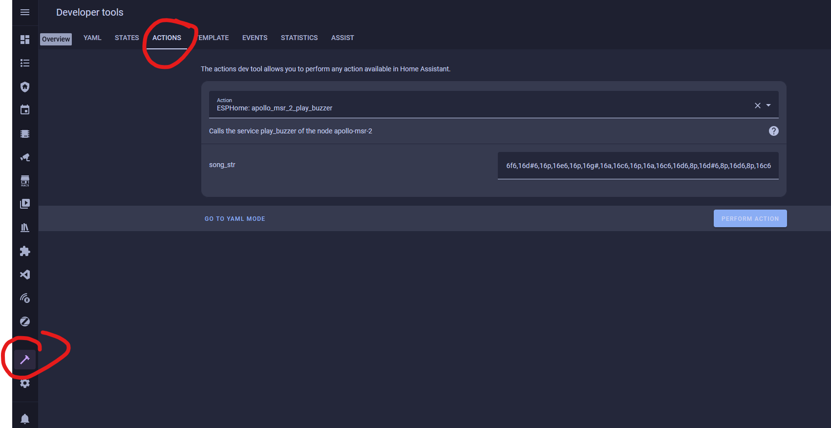
This guide will walk you through using the buzzer on your MSR-2. You can also use the "action" in an automation in Home Assistant.
- Open Home Assistant and navigate to developer tools in the bottom left

2. Click on services
3. Choose your MSR-2's buzzer (You can type in buzzer to find it easier)
4. Put a rtttl tone into the the string box
-
- Mario:
smb:d=4,o=5,b=100:16e6,16e6,32p,8e6,16c6,8e6,8g6,8p,8g,8p,8c6,16p,8g,16p,8e,16p,8a,8b,16a#,8a,16g.,16e6,16g6,8a6,16f6,8g6,8e6,16c6,16d6,8b,16p,8c6,16p,8g,16p,8e,16p,8a,8b,16a#,8a,16g.,16e6,16g6,8a6,16f6,8g6,8e6,16c6,16d6,8b,8p,16g6,16f#6,16f6,16d#6,16p,16e6,16p,16g#,16a,16c6,16p,16a,16c6,16d6,8p,16g6,16f#6,16f6,16d#6,16p,16e6,16p,16c7,16p,16c7,16c7,p,16g6,16f#6,16f6,16d#6,16p,16e6,16p,16g#,16a,16c6,16p,16a,16c6,16d6,8p,16d#6,8p,16d6,8p,16c6 - Cantina:
Cantina:d=4,o=5,b=250:8a,8p,8d6,8p,8a,8p,8d6,8p,8a,8d6,8p,8a,8p,8g#,a,8a,8g#,8a,g,8f#,8g,8f#,f.,8d.,16p,p.,8a,8p,8d6,8p,8a,8p,8d6,8p,8a,8d6,8p,8a,8p,8g#,8a,8p,8g,8p,g.,8f#,8g,8p,8c6,a#,a,g - Star Wars Imperial Death March:
StarWars/Imp:d=4,o=5,b=112:8d.,16p,8d.,16p,8d.,16p,8a#4,16p,16f,8d.,16p,8a#4,16p,16f,d.,8p,8a.,16p,8a.,16p,8a.,16p,8a#,16p,16f,8c#.,16p,8a#4,16p,16f,d.,8p,8d.6,16p,8d,16p,16d,8d6,8p,8c#6,16p,16c6,16b,16a#,8b,8p,16d#,16p,8g#,8p,8g,16p,16f#,16f,16e,8f,8p,16a#4,16p,2c# - Huge list: https://picaxe.com/rtttl-ringtones-for-tune-command/
- This is a good site to test rttl tones: https://adamonsoon.github.io/rtttl-play/
- Mario:
5. Click on the ACTIONS button in bottom right
How To Use The Apollo GPIO Header To Control An LED Strip
This tutorial will guide you through setting up one of our MSR-2 devices (works with any mezzanine port on any Apollo Device) with the optional $4.99 GPIO Header which adds pins for you to easily add functionality to your device! In this tutorial, however, we will be focusing on adding an LED strip to your Apollo device.
Materials Needed for tutorial:
- Apollo MSR-2, Apollo MTR-1, and all other future Apollo Automation products with the mezzanine port.
- Apollo GPIO Header
- ws2812b aka neopixel RGB led strip or similar. sk6812 RGBW strip will also work.
- Optional DuPont Cables for GPIO Header but any DuPont cables will do.
- USB-C cable and power brick to power MSR-2
You are limited to 300mA of power output from the 5v port. You can either attach an external power supply and power the MSR-2 via 5v and gnd pins or work with the limited power output of the port

Above is an image of the GPIO Header and its pinouts. We can use ports 2,4,6,7 for our data channel to an LED strip or multiple LED strips. We will also use the top two ports which are ground and 5v for power.
Did you know you can power the esp32 from the 5v and gnd pin? That means you can connect an external power supply and power it without the side USB port being used! This also allows for more power to be given to your LEDs!
We cannot use the IO ports 0,1,18, or 19 for LEDs but you can use ports 0 and 1 for i2c sensors.
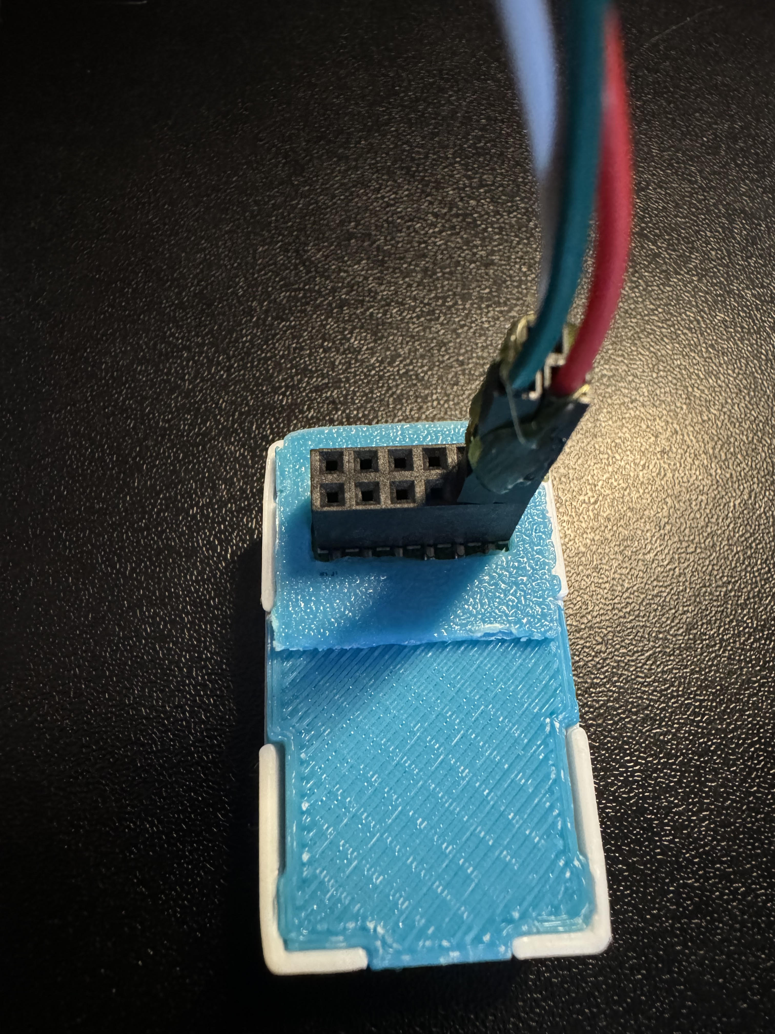
Connecting the GPIO Header to the MSR-2
The first thing we will do is remove our MSR-2 back plate and connect our GPIO Header to our MSR-2 and then put the new GPIO back plate on (blue).
Step 1. Remove the backplate of the MSR-2


Step 2. Line up the Xs shown on the msr-2 and the GPIO Header. They should both be facing in the same direction as shown below.

Step 3. Gently push down onto the GPIO Header as shown below:

Step 4. Confirm the GPIO Header is seated properly as shown below.

Step 5. Slide the GPIO Header back plate for the MSR-2 over your sensor and gently push down until it clicks into place.

If the back plate does not gently go onto the sensor please investigate and confirm it is in the right orientation.
Connecting DuPont pins to proper GPIO ports
Now we need to reference the GPIO pinout we looked at above and then connect three wires. You will need three male-to-male DuPont wires included in your kit. I suggest using red for power aka 5v, White for ground aka GND, and green for data aka port IO7. Most LED strips will also have this same color scheme and it's easier to match like colors together.


You can add a bit of hot glue to the Dupont wires to hold them together. DO NOT put hot glue into the GPIO Header's female pins that will ruin the addon. I am only suggesting that you can hot-glue the Dupont pins outer shell themselves together to stiffen them up.
Connecting DuPont pins to LED Strip
Next, we need to connect the other side of the Dupont pins to the LED strip. Most likely your LED strip will have a JST-SM connector which is a 3amp max connector with three wires connected: red for 5v, green for data, and white for gnd. We will be matching up our red, green, and white wires already attached to the GPIO add-on pins in the MSR-2 (using IO7 as the data pin for this tutorial)


Make sure to connect to the correct side of the LED strip. The led strip will have an arrow going down the led strip showing one direction for the data line. you want the data channel going FROM the msr-2 TO the led strip going in a "forward" direction as shown below.


Edit the YAML of your MSR-2 to let it know about your new LED strip
Finally, we need to tell the MSR-2 that we connected an LED strip. We need to tell it how many LEDs we have and we need to tell it that it's our second LED since the built-in LED is the first. This tutorial assumes you are comfortable with the ESPHome dashboard.
Step 1. Open ESPhome Dashboard and click edit to bring up the yaml your sensor is currently using.

You will see some YAML code here and you do NOT want to touch anything above line 20. If you need to, click your cursor at the end of wifi_password and hit enter to create a new line then make sure you backspace until you are "flush" with the line numbers like how wifi: is.
Step 2. Copy the code below and paste it to line 20 in your ESPHome yaml for this device.
light:
  - platform: esp32_rmt_led_strip
    id: bed_led
    name: "Bed LED"
    pin: GPIO7
    rmt_channel: 1
    default_transition_length: 0s
    chipset: WS2812
    num_leds: 60
    rgb_order: grb
    effects:
      - pulse:
          name: "Slow Pulse"
          transition_length: 1000ms
          update_interval: 1000ms
          min_brightness: 50%
          max_brightness: 100%
      - pulse:
          name: "Fast Pulse"
          transition_length: 100ms
          update_interval: 100ms
          min_brightness: 50%
          max_brightness: 100%
      - addressable_rainbow:

You change the rmt_channel to 1 because 0 is being used by the built-in LED of the MSR-2.
Step 5. Go into home assistant and confirm you now have a new light entity called Bed LED

Step 6. Click on the name "Bed LED" circled and it will pop up a color picker. You can then choose the color wheel option to pick any color of the rainbow, or select "effect" and choose an effect.


That's all folks! Thanks to Smart Home Sellout for putting this tutorial together!
MSR-2 Automation Guide
MSR-2 Examples From GitHub
MSR-2 Examples from GitHub
MSR-2 + Alarmo Home Security Install
My grandmother wanted a security system that would alert her when there was movement in her home after she had gone to bed. So, I set up three of our Apollo Automation mmWave sensors. These devices, plus the Alarmo add-on, quickly and easily allowed me to install a fully local, private, cloud-free, and no monthly subscription security system. She can arm/disarm it with one button on her Home Assistant dashboard, and it makes her feel much safer. This guide assumes you already have a motion/presence sensor installed on HA.
1. Install HACS
2. Install Alarmo and the Alarmo Card (Pretty Arm and Disarm card for your HA dashboard)
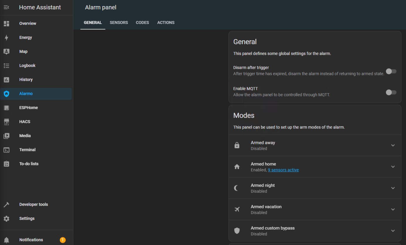
3. Find Alarmo on the left, select the Sensors tab, and toggle on the sensor entities that you would like to use for your alarm system.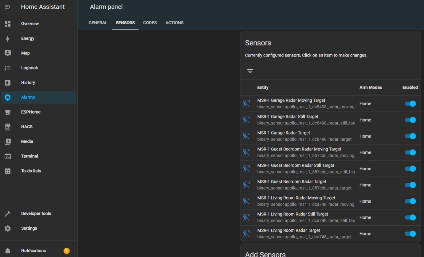
4. Now select the Actions tab and under Condition > Event > Select "Alarm is triggered". You can also select the device you would like to receive a notification on under Task > Target > Select Device (Phone, tablet, etc.)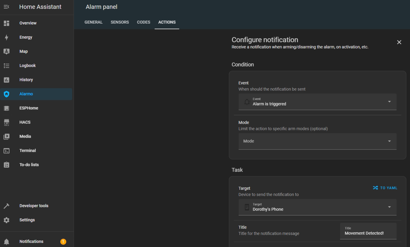
5. You can change the Title, Message, and Name of the alarm notification.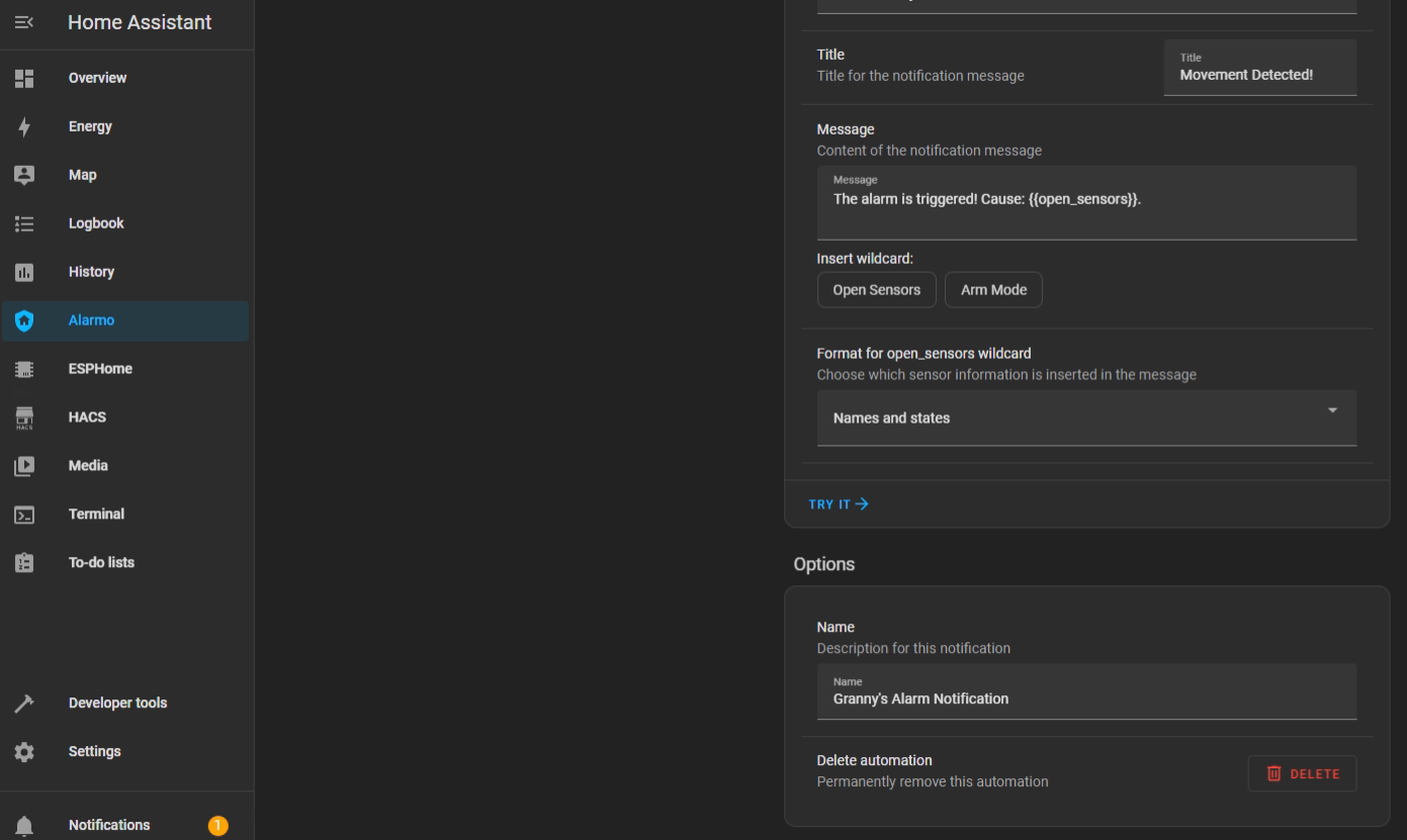
6. After saving that action we can add another one that will turn on our sensor lights and/or make the onboard piezo buzzers play an alarm sound. Uner Entity select your sensors RGB light.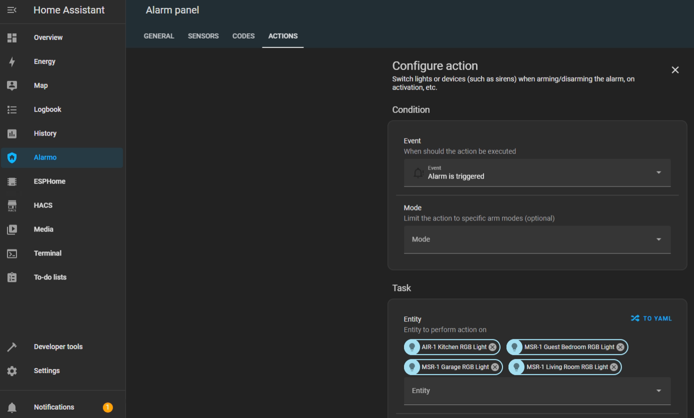
7. Under Action select Turn On and now your sensors RGB lights will turn on when the alarm is triggered.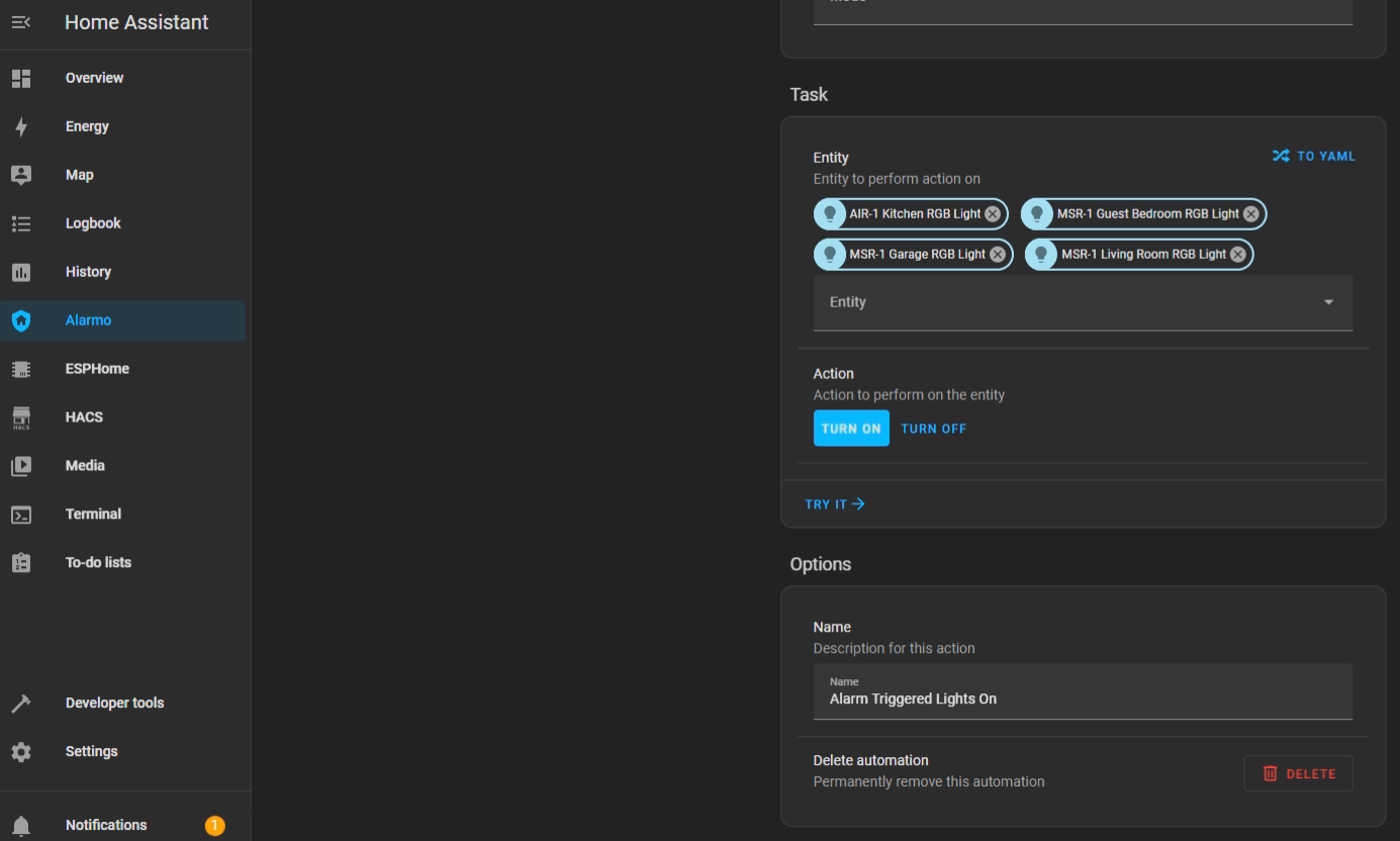
8. And that's it, seriously... Now you can enjoy a free and local security system.
We hope this was helpful and please let us know if there are any questions!