General
- Setup
- Getting Started
- Bluetooth Tracking
- Renaming Apollo Devices
- How To Change The Update Frequency Of Sensors/Force Update
- How To Add Temp And Humidity From SCD40
- Adjusting Wifi Power Save
- Calibrating And Updating
- Troubleshooting
- Wi-Fi Disconnecting
- Manually Uploading Code Through ESPHome
- Removing Device From Home Assistant
- Putting The MSR-1 In Boot Mode
- Connecting To Hidden Wifi Network
- Ubiquiti Unifi mDNS Auto Discover Issue
- Advanced Examples of Temperature & Humidity Offsets
- Apollo Automation YouTube Videos
- Sensor Comparisons
- Tutorials
- How To Use The Apollo GPIO Header To Control An LED Strip
- How to edit your Sensor's LUX update interval
- F.A.Q. ~ Frequenty Asked Questions
Setup
Getting Started
This will walk you through the process of connecting your new Apollo Automation sensor to Home Assistant through ESPHome. If at any point you get stuck, join our Discord for some help.
Connecting Through Hotspot
To connect through the sensor's onboard hotspot follow the below:
- Plug the sensor into a quality power brick. They require 5v and under an amp so most phone chargers will be fine. ESP devices are sensitive to power fluctuations and users have had some issues with really cheap power bricks. If your device is restarting or unavailable please try a different power brick.
- On your phone or PC, open the wifi settings and connect to "Apollo MSR-1 Hotspot", it might take a minute for the wifi network to show up
- Once connected it should automatically open a dashboard for your sensor
- If this does not automatically open the dashboard, please open your web browser and go to http://192.168.4.1
- Select the wifi network that you would like your sensor to connect to
- Input the wifi password. After connecting, the sensor's dashboard will automatically close. You've successfully connected your sensor, please check out the "Connecting Sensor To Home Assistant" section for the next steps.
Connecting To ESPHome Addon
You can connect to the ESPHome addon in Home Assistant to easily update your device. If you don't have ESPHome addon installed you can follow the steps here: Installing ESPHome Dashboard
Make sure to fill out your Wi-Fi details in the SECRETS section by clicking on the SECRETS Image below.
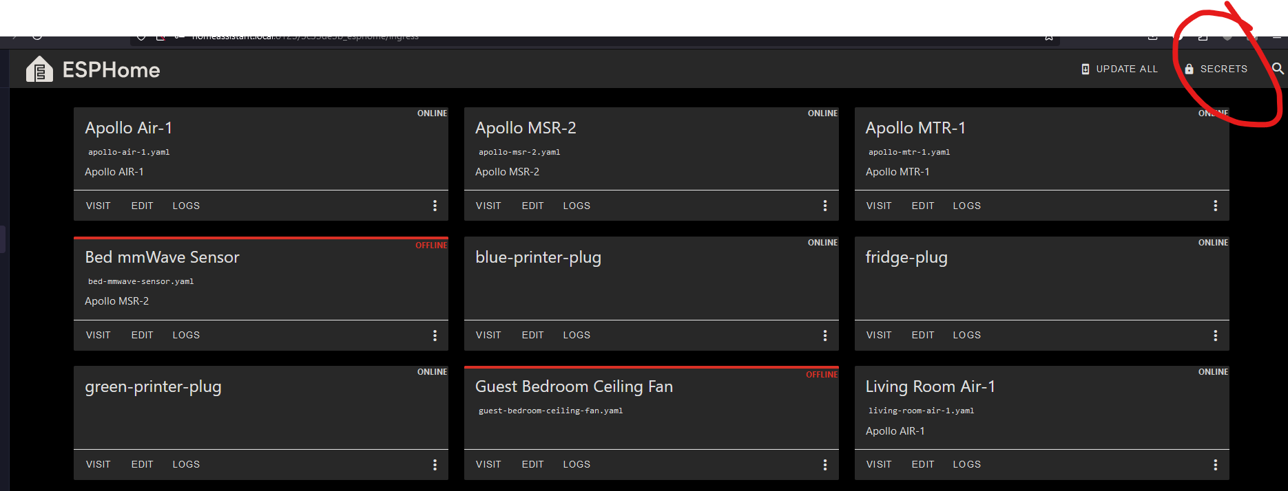
# Your Wi-Fi SSID and password - keep the quotes and just replace the name and password between the quotes!
wifi_ssid: "your-wifi-ssid-here"
wifi_password: "your-wifi-pass-here"-
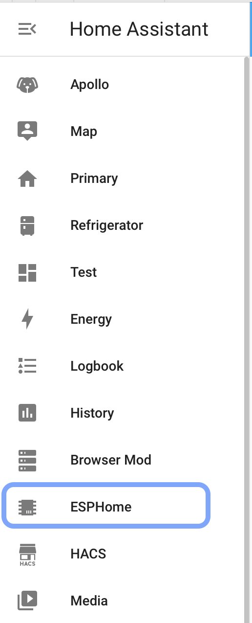
- Once installed you'll have the addon's icon on the left side of your HA instance:

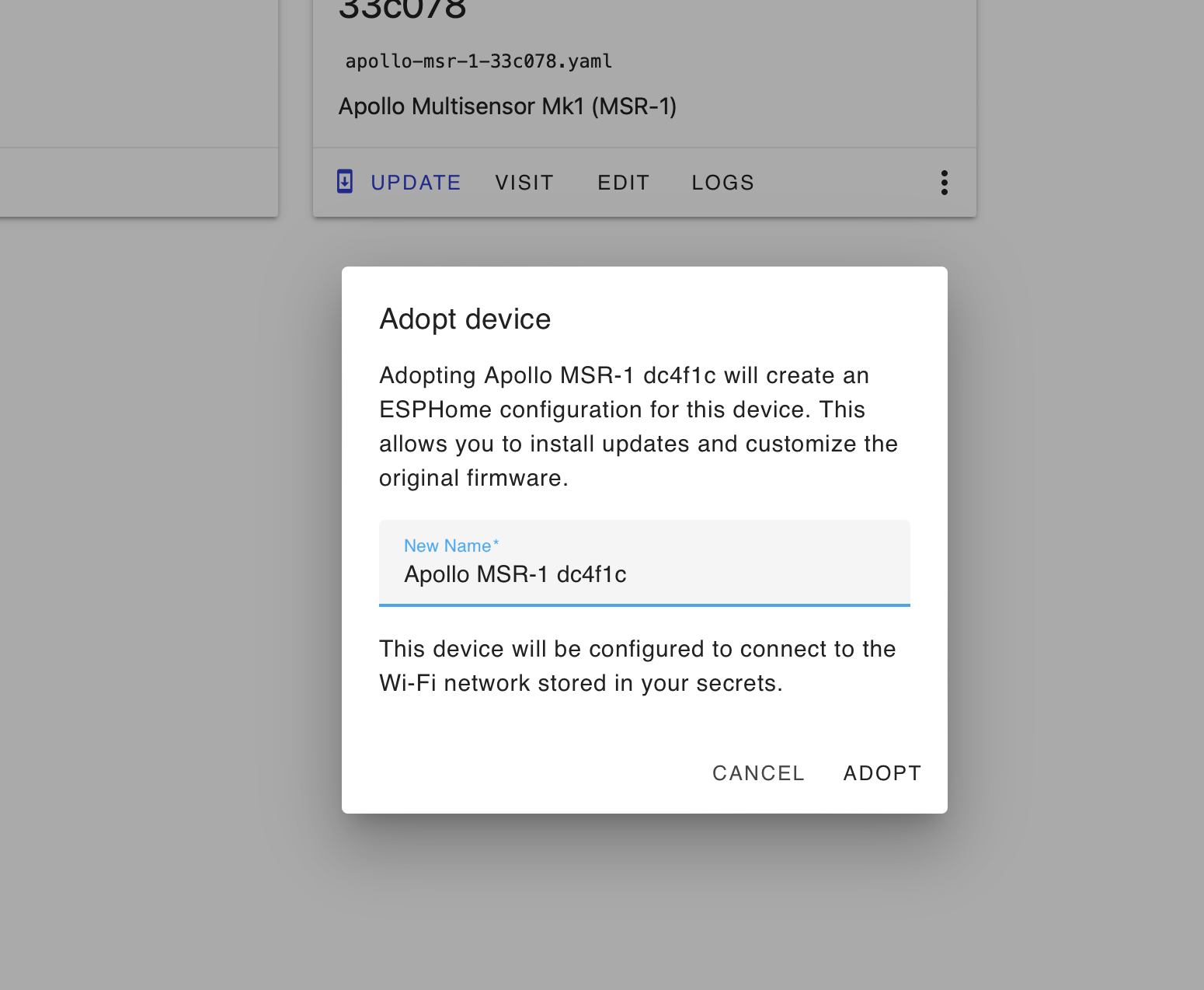
- Click on adopt for your sensor

- Then adopt again

Connecting Sensor To Home Assistant
-
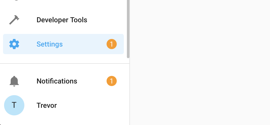
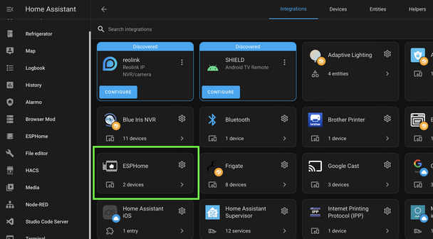
Once you connect your sensor to wifi through the above process, open up Home Assistant. Then in the bottom left click on “Settings”
-
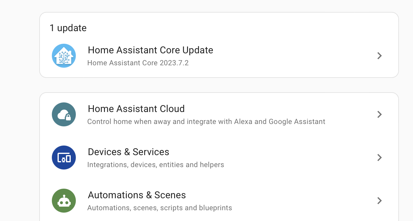
From there click on “Devices And Services”
-
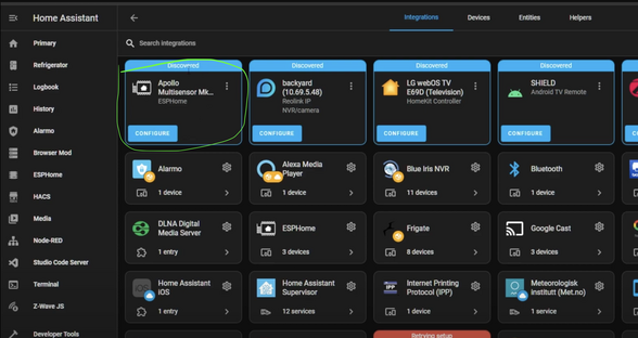
Look for the discovered sensor. It should be named “apollo-msr-mk1” with some random letters and numbers (Those come from the device's mac address). Click on “Configure” and then “Submit”.
-
If you do not see the device as discovered, make sure you have the ESPHome integration installed to Home Assistant you can find their instructions here
-
-
Add the sensor to ESPHome. It will now show up in the ESPHome integration
-
The sensor has now been added to Home Assistant and you can use it as you please. For ideas please visit our ideas section or join our Discord
6. Next steps:
Head on over to the CO2 Calibration page https://wiki.apolloautomation.com/books/general/page/co2-calibration to calibrate your new sensor.Note: This is not necessary if you did not purchase the CO2 sensor addon!
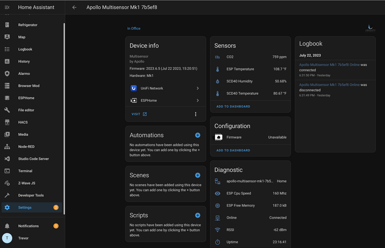
Sensors
You should now have the sensor added! If you have any problems or need help please join our Discord and post in the #support channel. Or just join to check out product development and community spotlights. Our team monitors that and can quickly respond there. Or visit our ideas section to find cool ways to display the information
Looking For Ideas On How To Use Your Sensor?
- Graph Co2 Over Time
- Turn The LED Red When C02 Is Over 1000 ppm
- Send You An Alert When Motion Is Detected After 11 pm
Or check out our #show-off channel in the Apollo Discord for community submissions
- Once installed you'll have the addon's icon on the left side of your HA instance:

Bluetooth Tracking
Apple iPhone/iWatch
Alternative HACS Integration: iPhone Detect
https://community.home-assistant.io/t/implement-espresense-fuctionality-in-home-assistant-taking-advantage-of-ble-proxy-of-esphome/524019/6
Thanks to user Jacob Pfeifer!
Ok, so looks like I've got signal strength tracking working for Apple watches by getting the mac address from the home assistant private ble device integration. Here's a quick write-up if anyone else is interested. The end of the doc has a complete configuration file example.
# Tracking an Apple Watch in esphome
Using esphome on an Apollo msr-1 to track an Apple Watch

## Acknowledgements:
The following github repo was used as a starting point for this configuration: https://github.com/dalehumby/ESPHome-Apple-Watch-detection

## RSSI Tracking
1.) Setup your apple watch in the "Private BLE Device" integration by following the instructions on the integration page: https://www.home-assistant.io/integrations/private_ble_device/

2.) Create a text sensor in the esphome config that grabs the apple watch current mac address from home assistant:
```yaml
text_sensor:
  - platform: homeassistant
    name: "Apple Watch Current MAC Address"
    id: apple_watch_mac
    entity_id: device_tracker.your_apple_watch_home_assistant_id
    attribute: current_address
```

3.)  Create a template sensor for storing and transmitting the rssi value:
```yaml
sensor:
  - platform: template
    id: apple_watch_rssi
    name: "Apple Watch RSSI"
    device_class: signal_strength
    unit_of_measurement: dBm
    accuracy_decimals: 0
    filters:
      - exponential_moving_average:
          alpha: 0.3
          send_every: 1
```

4.) Create a custom ble tracker that uses the mac address from home assistant to match the device:
```yaml
esp32_ble_tracker:
  scan_parameters:
    interval: 1.2s
    window: 500ms
    active: false
  on_ble_advertise:
    - then:
      - lambda: |-
          for (auto data : x.get_manufacturer_datas()) {
            if(x.address_str() == id(apple_watch_mac).state) {
              id(apple_watch_rssi).publish_state(x.get_rssi());
            }
          }
```

5) Ensure the power save mode for wifi is set to light (msr-1 defaults to using none which does not work with bluetooth tracking):
```yaml
wifi:
  power_save_mode: light
```

At this point if you install the changes on the device you should be successfully tracking the rssi for your apple watch. If you want you can optionally add some configuration for a basic presence detection sensor by doing the following:

## OPTIONAL PRESENCE DETECTION SECTION

6) Create configuration values for detection signal strength:
```yaml
number:
  - platform: template
    name: "RSSI Presence Level"
    id: rssi_present
    icon: "mdi:arrow-collapse-right"
    optimistic: true
    min_value: -100
    max_value: -35
    initial_value: -60
    step: 1
    entity_category: CONFIG
    restore_value: true
    update_interval: never
  - platform: template
    name: "RSSI Absence Level"
    id: rssi_not_present
    icon: "mdi:arrow-collapse-right"
    optimistic: true
    min_value: -100
    max_value: -35
    initial_value: -70
    step: 1
    entity_category: CONFIG
    restore_value: true
    update_interval: never
```

7) Create a sensor for storing and filtering the presence value:
```yaml
sensor:
  - platform: template
    id: room_presence_debounce
    filters:
      - sliding_window_moving_average:
          window_size: 3
          send_every: 1
```

8) Create a sensor for transmitting the filtered presence state:
```yaml
binary_sensor:
  - platform: template
    id: room_presence
    name: "Apple Watch Presence"
    device_class: occupancy
    lambda: |-
      if (id(room_presence_debounce).state > 0.99) {
        return true;
      } else if (id(room_presence_debounce).state < 0.01) {
        return false;
      } else {
        return id(room_presence).state;
      }
```

9) Update the rssi value to set the presence value when it receives a new rssi value:
```yaml
sensor:
  - platform: template
    id: apple_watch_rssi
    name: "Apple Watch RSSI"
    device_class: signal_strength
    unit_of_measurement: dBm
    accuracy_decimals: 0
    filters:
      - exponential_moving_average:
          alpha: 0.3
          send_every: 1
    on_value:
      then:
        - lambda: |-
            if (id(apple_watch_rssi).state > id(rssi_present).state) {
              id(room_presence_debounce).publish_state(1);
            } else if (id(apple_watch_rssi).state < id(rssi_not_present).state) {
              id(room_presence_debounce).publish_state(0);
            }
        - script.execute: presence_timeout  # Publish 0 if no rssi received
```

Now once you install the esphome changes you should be able to go to the device and set db values for the presence detection and also should see a presence sensor state.

## COMPLETE CONFIGURATION
A complete example of a configuration:
```yaml
substitutions:
  name: apollo-msr-1-6c7a64
  friendly_name: Living Room Multisensor
  roomname: Living Room
  yourname: Jacob

packages:
  ApolloAutomation.MSR-1: github://ApolloAutomation/MSR-1/Integrations/ESPHome/MSR-1.yaml
esphome:
  name: ${name}
  name_add_mac_suffix: false
  friendly_name: ${friendly_name}
api:
  encryption:
    key: xxxxxxxxxxxxxxxxxxxxxxxxxxxxxxxxxxxxxxxxxx


esp32_ble_tracker:
  scan_parameters:
    interval: 1.2s
    window: 500ms
    active: false
  on_ble_advertise:
    - then:
      - lambda: |-
          for (auto data : x.get_manufacturer_datas()) {
            if(x.address_str() == id(jacobs_watch_mac).state) {
              id(apple_watch_rssi).publish_state(x.get_rssi());
            }
          }
text_sensor:
  - platform: homeassistant
    name: "Apple Watch Current MAC Address"
    id: jacobs_watch_mac
    entity_id: device_tracker.jacob_s_apple_watch
    attribute: current_address

sensor:
  - platform: template
    id: apple_watch_rssi
    name: "$yourname Apple Watch $roomname RSSI"
    device_class: signal_strength
    unit_of_measurement: dBm
    accuracy_decimals: 0
    filters:
      - exponential_moving_average:
          alpha: 0.3
          send_every: 1
    on_value:
      then:
        - lambda: |-
            if (id(apple_watch_rssi).state > id(rssi_present).state) {
              id(room_presence_debounce).publish_state(1);
            } else if (id(apple_watch_rssi).state < id(rssi_not_present).state) {
              id(room_presence_debounce).publish_state(0);
            }
        - script.execute: presence_timeout  # Publish 0 if no rssi received

  - platform: template
    id: room_presence_debounce
    filters:
      - sliding_window_moving_average:
          window_size: 3
          send_every: 1


binary_sensor:
  - platform: template
    id: room_presence
    name: "$yourname $roomname Presence"
    device_class: occupancy
    lambda: |-
      if (id(room_presence_debounce).state > 0.99) {
        return true;
      } else if (id(room_presence_debounce).state < 0.01) {
        return false;
      } else {
        return id(room_presence).state;
      }

script:
  # Publish event every 30 seconds when no rssi received
  id: presence_timeout
  mode: restart
  then:
    - delay: 30s
    - lambda: |-
        id(room_presence_debounce).publish_state(0);
    - script.execute: presence_timeout

number:
  - platform: template
    name: "RSSI Presence Level"
    id: rssi_present
    icon: "mdi:arrow-collapse-right"
    optimistic: true
    min_value: -100
    max_value: -35
    initial_value: -60
    step: 1
    entity_category: CONFIG
    restore_value: true
    update_interval: never
  - platform: template
    name: "RSSI Absence Level"
    id: rssi_not_present
    icon: "mdi:arrow-collapse-right"
    optimistic: true
    min_value: -100
    max_value: -35
    initial_value: -70
    step: 1
    entity_category: CONFIG
    restore_value: true
    update_interval: never

wifi:
  power_save_mode: light
  ssid: !secret wifi_ssid
  password: !secret wifi_password
```
Android
Helpful links:
ESP32 Bluetooth Low Energy Tracker Hub
iBeacon support for ble_presence
ESP32 Bluetooth Low Energy Beacon
iBeacon Region
- Install the iBeacon integration in HA
iBeacon Install Guide - Install the Home Assistant App on your device
Android
Apple - Navigate to the HA settings
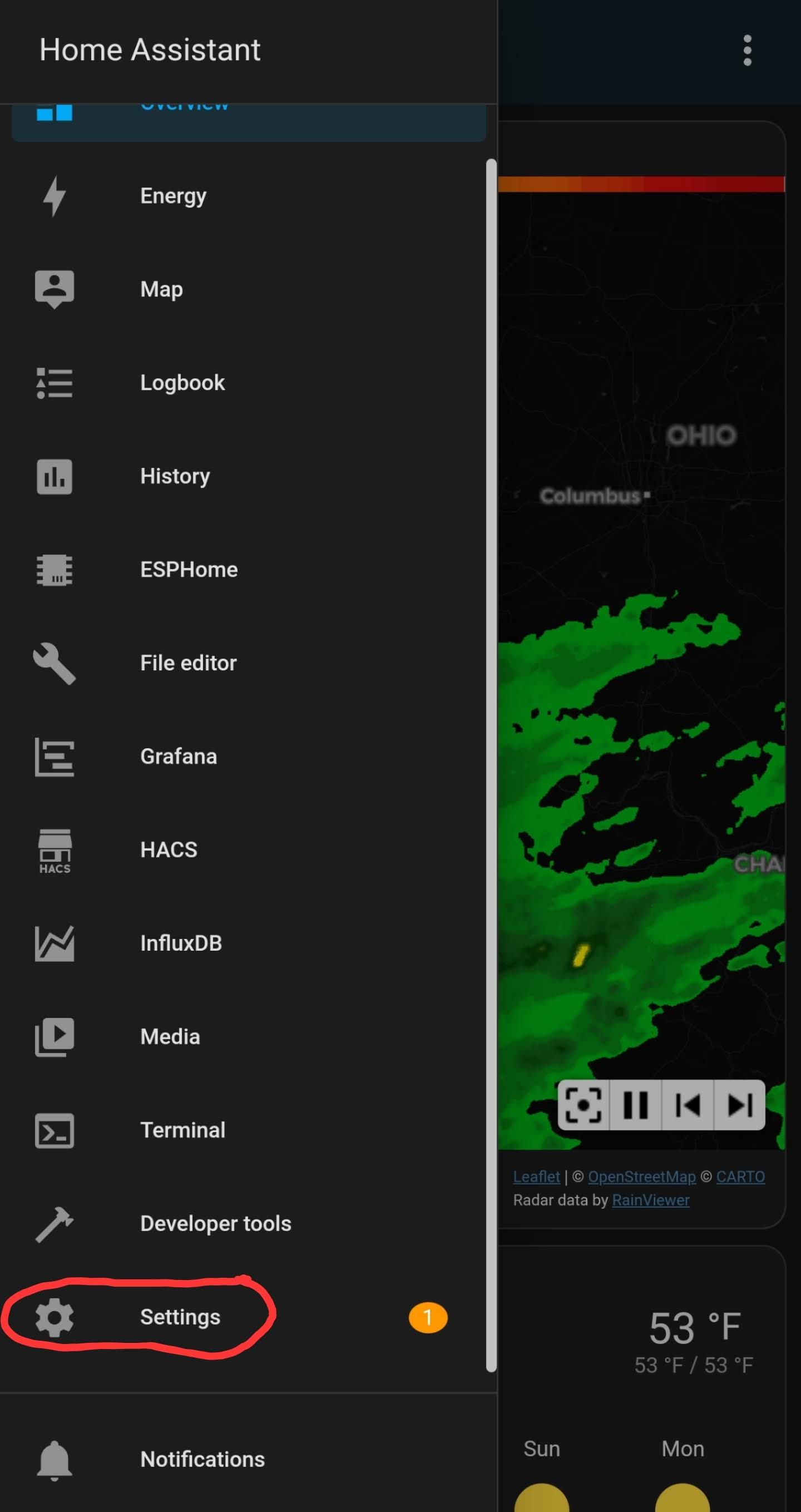
- Select Companion app
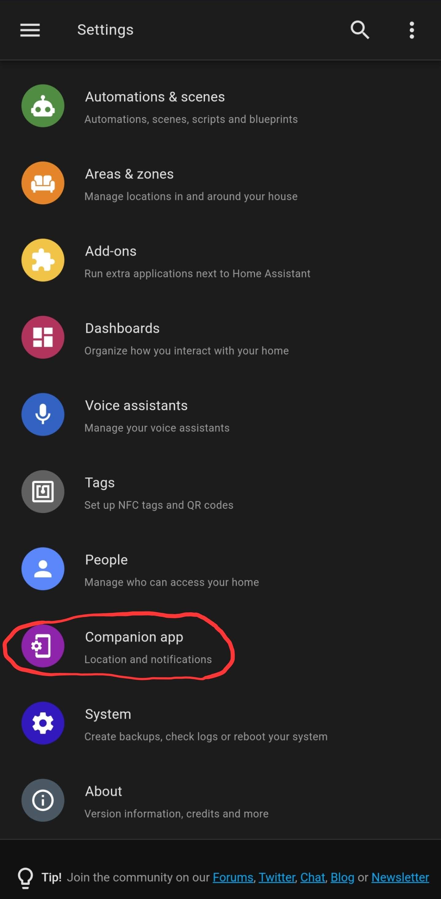
- Select Manage sensors
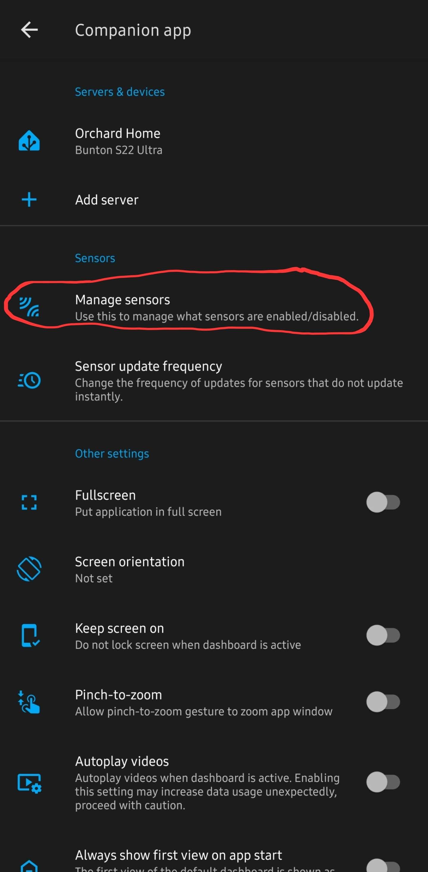
- Turn on the "BLE Transmitter"
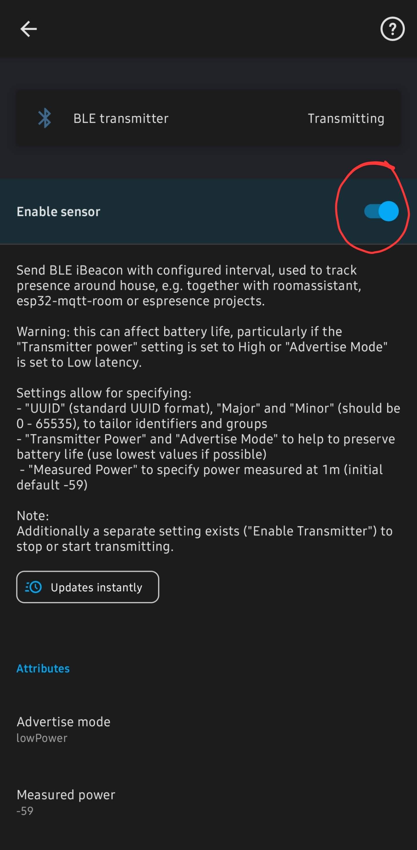
- After opening BLE transmitter and turning it on, then scroll down to get the iBeacon unique ID
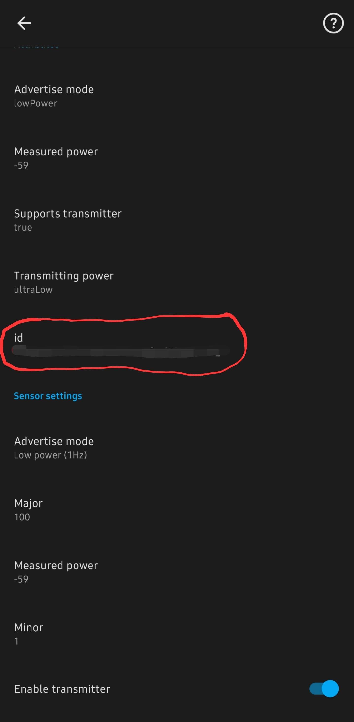
- Add it to the ESPHome yaml config for the MSR-1
- Be sure to add "power_save_mode: LIGHT" to the wifi section
# Example config.yaml wifi: ssid: !secret wifi_ssid password: !secret wifi_password power_save_mode: LIGHT esp32_ble_tracker: binary_sensor: - platform: ble_presence ibeacon_uuid: '77a6438d-ea95-4522-b46c-cb2b4412076f' ibeacon_major: 100 ibeacon_minor: 1 name: "Jane's Phone" - Should be all set!


Thanks to our Discord user albuquerquefx for the information below!
For those interested in using their MSR-1 as a Bluetooth proxy while also actively scanning for BLE devices, you'll need to add the following to your ESP32 YAML file (I'm using a 1.5-second scan interval with a 750ms window for sensing BLE beacons):
esp32_ble_tracker:
id: ${name}_ble_tracker
scan_parameters:
interval: 1500ms
window: 750ms
active: true
bluetooth_proxy:
active: true
Additionally, you need to include this entry in your existing Wi-Fi section:
power_save_mode: light
Once complete, after a few minutes within the presence of any iBeacon device within listening distance of your MSR-1, Home Assistant should announce the presence of an iBeacon Tracker integration on your settings page. While I didn't capture a screenshot of it, it's now installed and sensing things.
If you encounter a device with a blank name (e.g., anything Android), you'll need to click "Configure" and enter the UUID manually. This is because Home Assistant does not allow devices with empty names (interestingly, their own companion app permits forcing an Android to become an iBeacon but then doesn't require a name field).
For devices where you don't know the IRK, you may have to wait about 300 seconds for your iBeacon Tracker to process 10 different iterations of the same UUID but with the last four characters randomly changed. Once ten instances have appeared, the iBeacon Tracker integration should recognize they're all the same device and combine them into a single tracker element. Just be patient, though it can be a bit frustrating.
Renaming Apollo Devices
ESPHome Integration
1. Go to settings and select Devices & services

2. Select ESPHome

3. Select the three dots next to the device and select Rename

4. Rename the device and select OK

ESPHome Addon
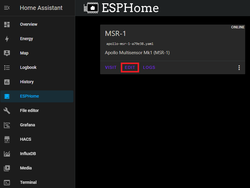
1. Select the ESPHome addon in the sidebar
2. Select Edit on the device you want to rename

3. Chane the friendly_name and save it

These new names can be used in automations.

Full Renaming
Thanks to Panzer from our Discord.
- Install the first MSR-1 using the standard method to get a default ESPHome configuration.
- Edit this configuration to update the "name" and "friendly name" as desired.
- SSH into the ESPHome directory and copy this configuration six times, then modify each copy with unique names, friendly names, and API keys. (Can also use VSCode/File Editor to copy the configuration from the ESPHome folder)
- Delete the initially defined sensor in ESPHome and devices (if added there), and possibly reboot.
- Now with six distinct configs, use the 'install' option in ESPHome, select "plug into this computer", and connect the MSR-1 to your computer.
- Download the generated "factory-image" from ESPHome on Home Assistant (HA) and flash it. This will install the sensors without MAC-based names.
- Repeat the process for the remaining sensors.
- Add the sensors to devices if they are discovered.
- Can now update the sensors wirelessly again.


Alternative Method
Thanks to lpbaud from our Discord.
Instead of changing the name as your document suggests, you can go to System > Devices and Services > Devices, then click the device you want to rename. Next, click the pencil icon in the upper right corner of the screen and rename the device there. Doing it this way, after you click "Update," it will ask if you want to change the entity ID, as shown in the picture above. If you click "Update" here, it will change all the entity IDs, like in the other picture above.
Here's another tip for using this naming scheme or a similar one in Node-RED: In the Entity State node dialog, if you click the empty box labeled "Entity," a small box will open beneath it displaying a list of all the available entity names, in no particular order. If you start typing in that box, it filters the list based on what you type. So, if my kitchen MSR is named msr-k and I want to trigger an event based on the value of radar target, I would type "-k target." The space between words acts as a wildcard, so the list is filtered by everything containing "-k" and "target," allowing you to select the one you need. Quite handy.
How To Change The Update Frequency Of Sensors/Force Update

3. Insert your code (The example below is for our AIR-1 SEN55 sensor)
sensor:
  - platform: sen5x
    id: !extend sen55
    update_interval: 5s
4. In the top right of the same screen Select Save and then Install
5. If it compiles correctly then you should see a green Success

6. When you see the sensor logs, you are finished and can select Stop

7. Now your sensor value should update!
Force Update
Follow the same steps above but use this code to force the sensor to update.
sensor:
- platform: sen5x
  id: !extend sen55
  nox:
    name: "SEN55 NOX"
force_update: TrueHow To Add Temp And Humidity From SCD40
3. Insert your code (The example below is for our AIR-1 SEN55 sensor but this applies to MSR-1/2, MTR or any sensor with the CO2 module)
sensor:
  - platform: scd4x
    id: !extend scd40
    temperature:
      name: "SCD40 Temperature"
    humidity:
      name: "SCD40 Humidity"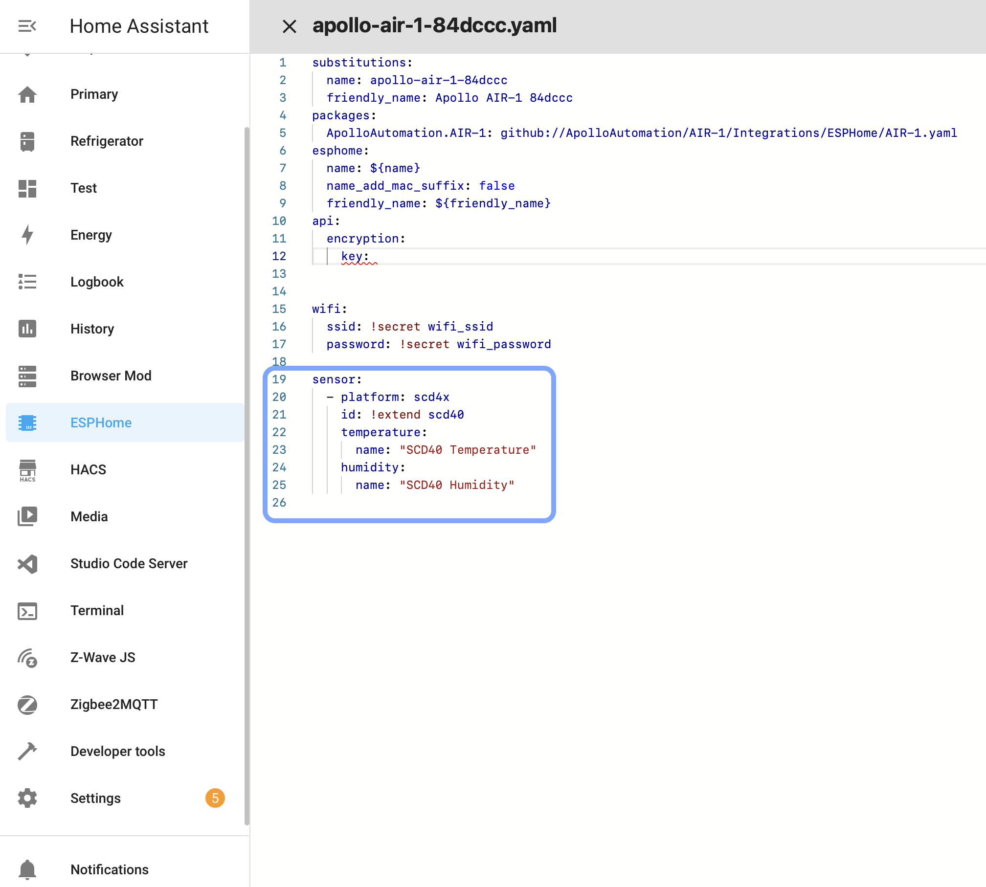
4. In the top right of the same screen Select Save and then Install
5. If it compiles correctly then you should see a green Success
6. When you see the sensor logs, you are finished and can select Stop
7. Now your sensor value should update!
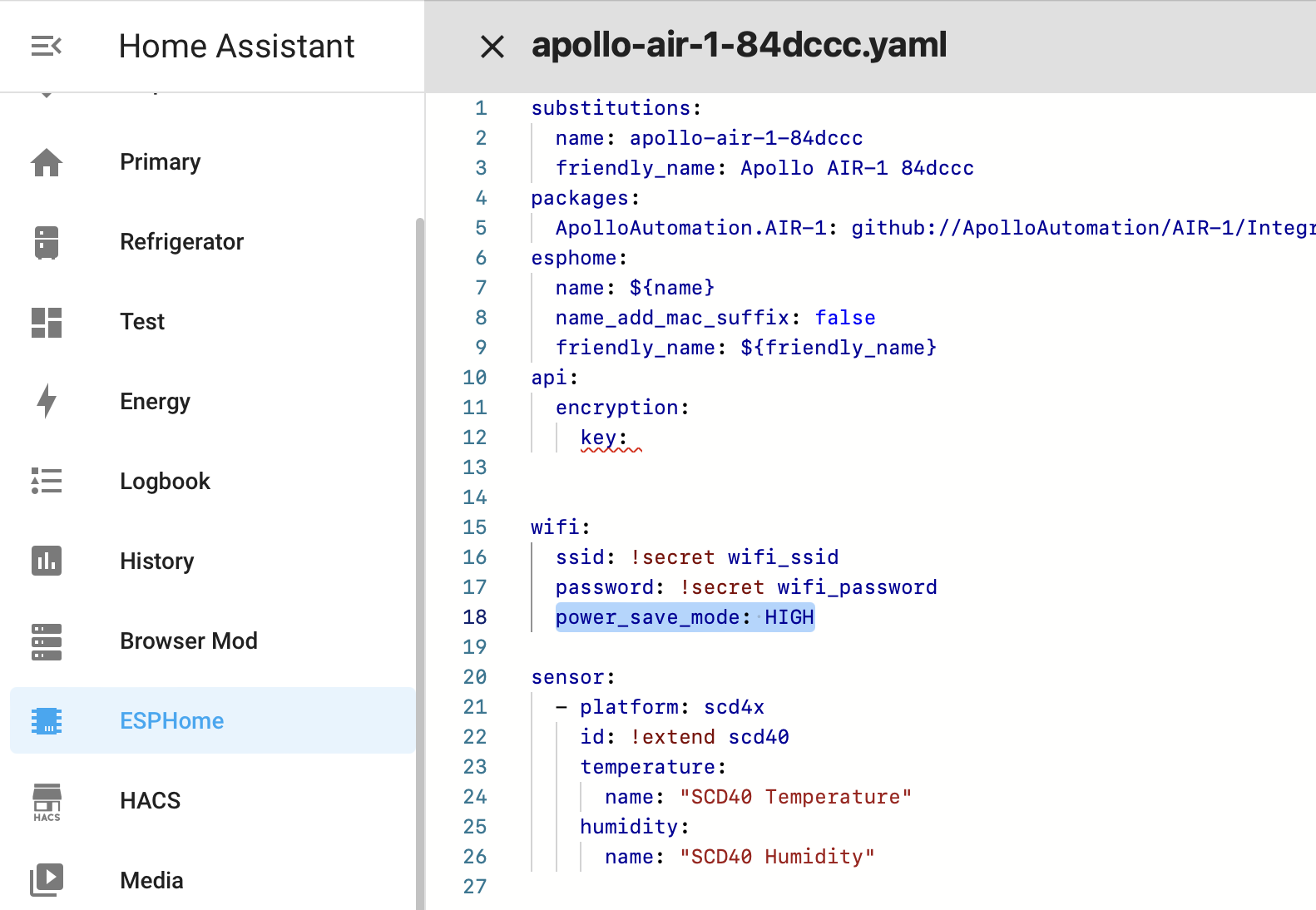
Adjusting Wifi Power Save
The ESP chips produce a significant amount of energy constantly using wifi. Here is how to adjust the wifi power save mode
- In ESPHome's addon, click on "Edit" for the sensor you want to adjust
-
- Add the code to adjust the power
-
wifi: ssid: !secret wifi_ssid password: !secret wifi_password power_save_mode: HIGH -

-
- In the top right, click on "Save" then "Install"
Calibrating And Updating
Updating Firmware
Updating Through ESPHome Addon
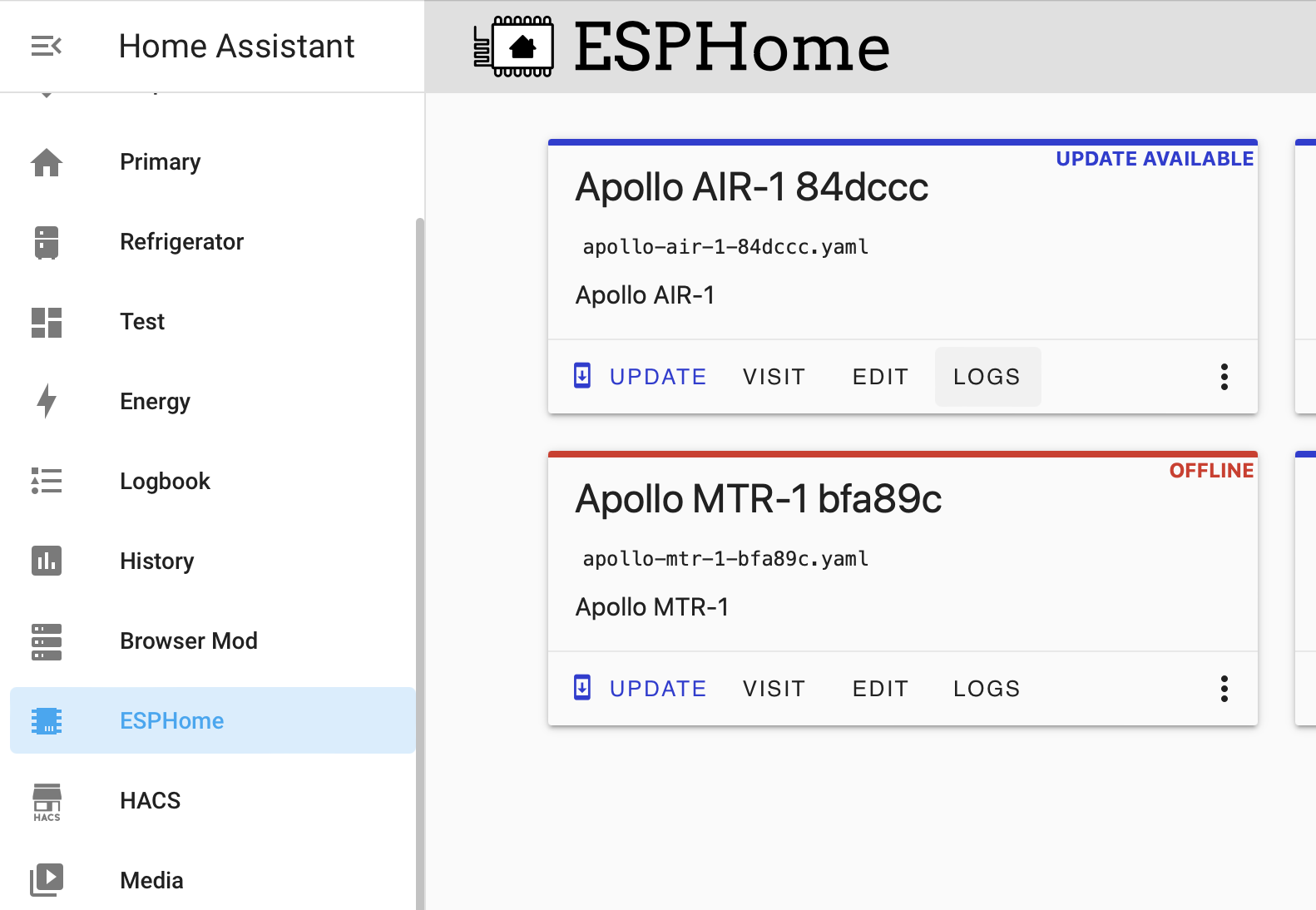
- In HomeAssistant open the ESPHome addon
- Or click this to Open your Home Assistant instance and show the dashboard of the ESPHome add-on.
- Make sure you are running the latest version of ESPHome
- On older hardware, it will not auto-update so you will have to uninstall and reinstall ESPHome
- Find the sensor you want to update and click the three dots in the bottom right

5. Select “Validate” from the list

6. Once the validation completes, click “Install” in the bottom right

7. Complete!
CO2 Calibration
1. Take your sensor outside (for a walk :D) and plug it in. Make sure it is connected to Home Assistant and let it sit powered on for 3-5 minutes outside before starting the calibration.


3. Select Devices & Services

4. Select ESPHome

5. Find your sensor and click on the blue “1 device” link

6. Press the Calibrate SCD40 button and you are all set!
If you do not see this button, either update your firmware or refer to this older revision
It can take a few times clicking the calibrate for it to equalize correctly. If you don't see the SCD40 reporting 400-500 ppm then click it again.

7. Now your CO2 sensor should be calibrated! Be sure to setup some nice cards on your dashboard so you can monitor the CO2 levels. My bedroom's CO2 levels got dangerously high and I had to run my HVAC more frequently at night to circulate the air. See examples of cards and data below.
Example Home Assistant Card

Dangerous CO2 levels in bedroom. Steep decline in level due to opening door, window and running fan.

Wisconsin Department of Health CO2 Level Chart

CO2 levels staying below 1500 ppm after changing HVAC fan schedule to circulate air more frequently. Need to increase air exchange to get below 1000 ppm for a safer environment.

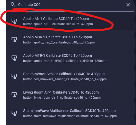
CO2 Calibration - The Quick method - Desktop Only not mobile
This article will guide you through a simple calibration of your CO2 sensor for any Apollo Automation device!
- Go to your home assistant dashboard and hit the letter "e" - It will pop up with an entity filter and here we will type in "Calibrate CO2" and select the correct device.
*HINT* If you cannot get this menu to pop-up, click somewhere on the home assistant dashboard then press your "e" key *HINT*
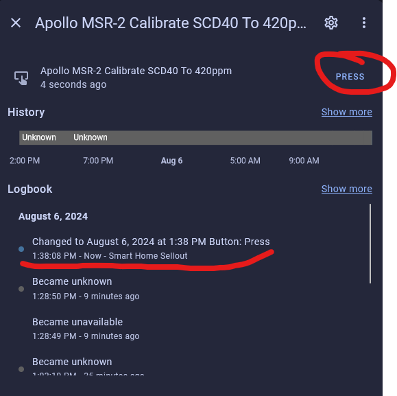
- DO NOT RUSH THIS Go Plug your sensor in outside and let it sit for 5 minutes or more to get normalized readings DO NOT RUSH THIS
- Click on the button that says "PRESS" and then you are done.
4. Go get your sensor from outside and plug your sensor in wherever you want it!
Troubleshooting
Wi-Fi Disconnecting
- Try a couple of different power cord and power brick combinations - this matters a lot more than you'd think!
- Check to see if the sensor's hotspot is showing up. (this means it is not connected to a network)
- Check the router's connected devices - the device will show up with the Apollo name and a 6 digit hex value of the end of the mac address.
- Disable power save mode in esphome Power Save Mode.
Manually Uploading Code Through ESPHome
If your device becomes unresponsive and you've exhausted the other troubleshooting methods you can upload a fresh set of firmware by following the below guide. The utility does need to be run from Chrome or Edge.
-
Plug your MSR-1 into your computer with a quality USBC cable that supports data transfer
-
Navigate to the installer page for your specific product (i.e. Air-1) and click connect ** MSR-1 or MSR-2 or AIR-1 or MTR-1 **
-
Select your Apollo device, it will show with a similar name to the one below, and click connect. If you aren't sure which device it is, you can unplug the MSR-1 and see which disappears.

If no device shows, click cancel and then install the recommended driver that shows on the popup. If you have installed the driver, tried different cables, and it still won't work refer here for putting the MSR-1 in bootloader mode and then retry step 3. Putting MSR-1 In Boot Mode Document
- Choose to install the new firmware

- Wait for the installer to finish

-
After finishing, check for the Apollo hotspot and connect. This might not show if you previously had the MSR-1 connected to your wifi
-
Log into Home Assistant and go to the ESPHome addon check to see if you can adopt the device.

Removing Device From Home Assistant
This will cover how to remove an Apollo device from Home Assistant

2. On the device you would like to remove, click the three dots and select "Delete"

3. Go to Settings --> Devices & Services --> ESPHome

4. On the device you would like to remove, click the three dots and then "Delete"

5. Restart your Home Assistant

It can take a few minutes for your Home Assistant instance to start back up
Putting The MSR-1 In Boot Mode
This will cover how to put the MSR-1 into boot mode. This is sometimes needed for uploading new firmware if the device is struggling.
- Unplug the device
- Slide the back case off
- Pull the device out of the case
- Plug back into your computer
- Press and hold the boot button, while holding it press and release the reset button, then release the boot button

6. Continue on with uploading firmware document
Connecting To Hidden Wifi Network
- Setup your device using a regular wifi network
- In Home Assistant go to your ESPHome add-on
- On your sensor click on edit
- Change the wifi section to look like the below but with your wifi credentials

4. Save and install to your device
Ubiquiti Unifi mDNS Auto Discover Issue
If mDNS is unchecked then Home Assistant and ESPHome will not auto discover new devices. Also, if you have different networks that Home Assistant and ESPHome devices are on, then you will need mDNS on both networks and firewall rules between them. (Thank you to the Ubiquiti Discord member Blue!) Below are guides for using your PC and the Unifi Network mobile app to fix this issue.
Quick Guide
- Settings > Network > Multicast Settings > Select the networks you want mDNS/IGMP Snooping on
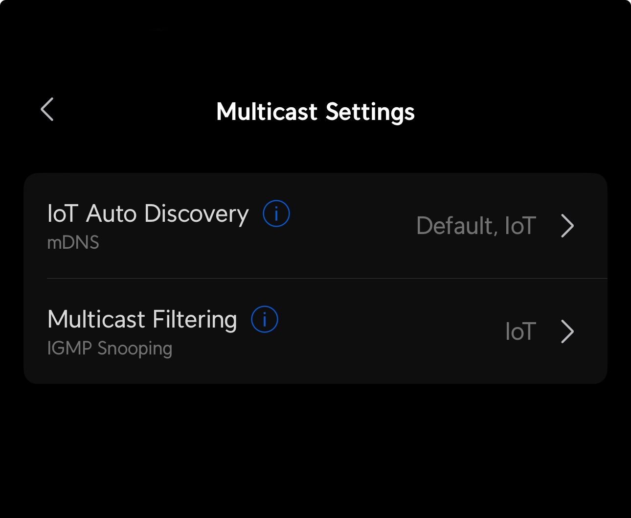
(Thank you to the Ubiquiti Discord member MK!)
Steps for PC
1. Log into your Unifi network through your default IP address which is usually 192.168.1.1
2. Select Network

3. Select Settings

4. Select Networks

5. Select the Default Network

6. Check Multicast DNS

7. Now the Home Assistant/ESPHome auto-discover issue should be fixed!
8. If this does not work then you can also try checking IGMP Snooping (checkbox above Multicast DNS) on your IoT networks.
Steps for the Unifi Network Mobile App
1. Open the Unifi Network app

2. Tap Settings/Gear Icon

3. Tap Networks

4. Tap Default Network

5. Tap the Multicast DNS slider

6. Now the Home Assistant/ESPHome auto-discover issue should be fixed!
Advanced Examples of Temperature & Humidity Offsets
Simple Offsets for Temperature and Humidity:
Please add these to the bottom of your esphome yaml for your device then click save and install. Once you are finished, you will have two new boxes inside the home assistant esphome integration device page for your device where you can fill in an offset. Give them up to 1minute to take effect!
sensor:
  - id: !extend scd40
    humidity:
      name: "Humidity"
      id: "humidity"
      filters:
        - lambda: return x - id(scd40_humidity_offset).state;
    temperature:
      name: "Temperature"
      id: "temperature"
      filters:
        - lambda: return x - id(scd40_temperature_offset).state;
number:
  - platform: template
    name: SCD40 Humidity Offset
    id: scd40_humidity_offset
    restore_value: true
    initial_value: -18.86
    min_value: -70.0
    max_value: 70.0
    entity_category: "CONFIG"
    unit_of_measurement: "%"
    optimistic: true
    update_interval: never
    step: 0.1
    mode: box
  - platform: template
    name: SCD40 Temperature Offset
    id: scd40_temperature_offset
    initial_value: 14.54
    min_value: -70.0
    max_value: 70.0
    entity_category: "CONFIG"
    unit_of_measurement: "°C"
    optimistic: true
    update_interval: never
    step: 0.1
    mode: box
BME280 & SCD40 Sensors: Overcoming Temperature & Humidity Reading Challenges
The BME280 and SCD40 sensors are known for their precision in measuring temperature and humidity. However, like all sensor systems, they can sometimes provide inaccurate readings due to various factors. In the case of the BME280 and SCD40 sensors, one significant challenge arises from the heat produced by the ESP chip, which can alter the environment inside its enclosure, thereby skewing the readings.
Adjusting the BME280 and SCD40 Temperature Offset
For users who want to fine-tune their sensors, the BME280 and SCD40 Temperature Offset entities can be manually adjusted to match the conditions in their home. The offset values are subtracted from the raw temperature & humidity readings in the firmware to update the sensor readings in the home assistant entity. For example: scd40_temperature entity = raw scd40 temperature reading - scd40_offset.
By default, these offsets are preset to values based on our NIST certified thermometer, it's important to note that these values are calibrated for our environment. They might not be accurate for all settings. Therefore, by using a reference thermometer, users can adjust the difference between the readings to get a more accurate representation.
Users will also notice the bme280_humidity_calibrated, scd40_humidity_calibrated, bme280_temperature_calibrated, and scd40_temperature_calibratedentities. These values utilize the linear filter in the ESPHome firmware to adjust the readings based on our collected data. Again, due to environmental differences, these might not always be precise.
Modeling the Relationship Between Sensors
Another approach to getting accurate readings is to model the relationship between the ESP temperature and the other sensors compared against a reference temperature. This can be achieved by creating a template sensor in Home Assistant that employs a decision tree or our regression coefficients.
Here's an example that can be added to a configuration YAML:
sensor:
  - platform: template
    sensors:
      estimated_reference_temperature:
        friendly_name: "Estimated Temperature"
        unit_of_measurement: '°C'
        value_template: >
          {{
            0.3228 * states('sensor.apollo_msr_1_a79e24_esp_temperature') | float +
            0.8702 * states('sensor.apollo_msr_1_a79e24_scd40_temperature') | float +
            -0.1285 * states('sensor.apollo_msr_1_a79e24_bme280_temperature') | float +
            -0.0491 * states('sensor.apollo_msr_1_a79e24_scd40_humidity') | float +
            0.0851 * states('sensor.apollo_msr_1_a79e24_bme280_humidity') | float +
            -17.4840
          }}


      estimated_reference_humidity:
        friendly_name: "Estimated Humidity"
        unit_of_measurement: '%'
        value_template: >
          {{
            -1.2468 * states('sensor.apollo_msr_1_a79e24_esp_temperature') | float +
            -2.1959 * states('sensor.apollo_msr_1_a79e24_scd40_temperature') | float +
            2.9604 * states('sensor.apollo_msr_1_a79e24_bme280_temperature') | float +
            0.2380 * states('sensor.apollo_msr_1_a79e24_scd40_humidity') | float +
            1.8283 * states('sensor.apollo_msr_1_a79e24_bme280_humidity') | float +
            40.1686
          }}
For users who want to gather their own data with a reference sensor and MSR-1 within their home, we recommend logging data to a CSV using the following YAML entries:
#Configuration.yaml
notify:
  - platform: file
    name: sensor_csv_log
    filename: /config/sensor_log.csv
    timestamp: False

#Automations.yaml
  - id: log_sensor_data_to_csv
    alias: "Log Sensor Data to CSV"
    trigger:
      platform: time_pattern
      minutes: "/1"  # Log data every minute to match reference sensor
    action:
      - service: notify.sensor_csv_log
        data_template:
          message: >
            {{ now().strftime('%Y-%m-%d %H:%M:%S') }},
            {{ states('sensor.apollo_msr_1_a79e24_esp_temperature') | default('NA') }},
            {{ states('sensor.apollo_msr_1_a79e24_scd40_temperature') | default('NA') }},
            {{ states('sensor.apollo_msr_1_a79e24_bme280_temperature') | default('NA') }},
            {{ states('sensor.apollo_msr_1_a79e24_scd40_humidity') | default('NA') }},
            {{ states('sensor.apollo_msr_1_a79e24_bme280_humidity') | default('NA') }},
            {{ states('number.apollo_msr_1_a79e24_bme280_temperature_offset') | default('NA') }},
            {{ states('number.apollo_msr_1_a79e24_scd40_humidity_offset') | default('NA') }},
            {{ states('number.apollo_msr_1_a79e24_bme280_humidity_offset') | default('NA') }},
            {{ states('number.apollo_msr_1_a79e24_scd40_temperature_offset') | default('NA') }},
            {{ states('sensor.apollo_msr_1_a79e24_uptime') | default('NA') }}
The Interrelation of Temperature and Humidity
It's important to understand that temperature and humidity share an interdependent relationship. When the air temperature rises, its capacity to hold moisture increases, which can decrease relative humidity levels. Conversely, when the temperature falls, the air's capacity to hold moisture decreases, leading to increased humidity. This relationship plays a significant role in how sensors detect and interpret readings, making it even more crucial to ensure accuracy.
Advanced Accuracy with GPIO
For those seeking the highest accuracy, an advanced solution is available. The exposed mezzanine connector on the back of our Apollo boards can be utilized to connect a temperature/humidity sensor. This modification can dramatically improve both temperature and humidity readings, providing data that's as accurate as possible.
Apollo Automation YouTube Videos
Apollo Automation Workshop Tour
Home Assistant Green Unboxing
Sensor Comparisons
Tutorials
How To Use The Apollo GPIO Header To Control An LED Strip
This tutorial will guide you through setting up one of our MSR-2 devices (works with any mezzanine port on any Apollo Device) with the optional $4.99 GPIO Header which adds pins for you to easily add functionality to your device! In this tutorial, however, we will be focusing on adding an LED strip to your Apollo device.
Materials Needed for tutorial:
- Apollo MSR-2, Apollo MTR-1, Apollo Air-1 and all other future Apollo Automation products with the mezzanine port.
- Apollo GPIO Header
- ws2812b aka neopixel RGB led strip or similar. sk6812 RGBW strip will also work.
- Optional DuPont Cables for GPIO Header but any DuPont cables will do.
- USB-C cable and power brick to power MSR-2
You are limited to 300mA of power output from the 5v port. You can either attach an external power supply and power the MSR-2 via 5v and gnd pins or work with the limited power output of the port

Above is an image of the GPIO Header and its pinouts. We can use ports 2,4,6,7 for our data channel to an LED strip or multiple LED strips. We will also use the top two ports which are ground and 5v for power.
Did you know you can power the esp32 from the 5v and gnd pin? That means you can connect an external power supply and power it without the side USB port being used! This also allows for more power to be given to your LEDs!
We cannot use the IO ports 0,1,18, or 19 for LEDs but you can use ports 0 and 1 for i2c sensors.
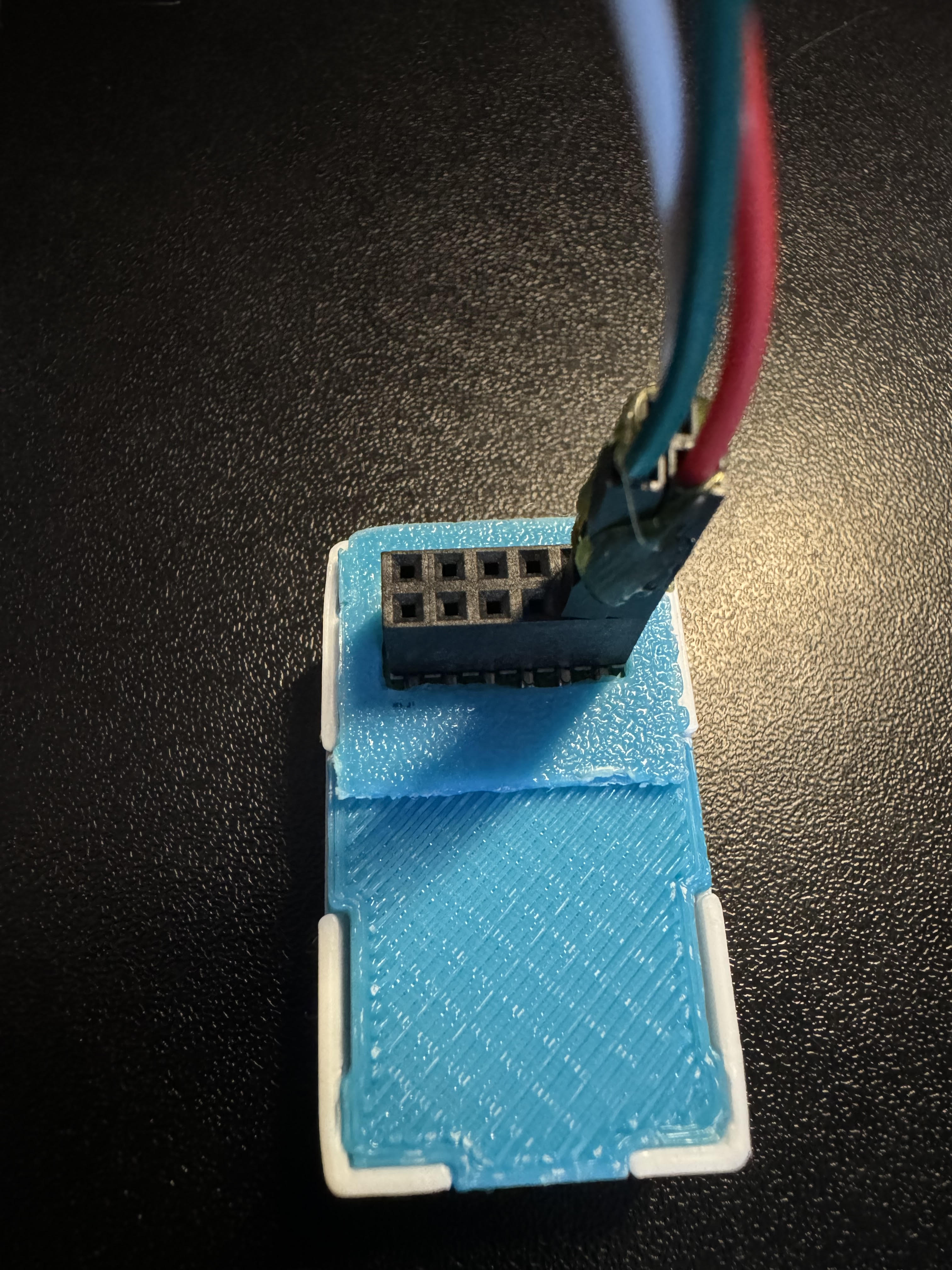
Connecting the GPIO Header to the MSR-2
The first thing we will do is remove our MSR-2 back plate and connect our GPIO Header to our MSR-2 and then put the new GPIO back plate on (blue).
Step 1. Remove the backplate of the MSR-2


Step 2. Line up the Xs shown on the msr-2 and the GPIO Header. They should both be facing in the same direction as shown below.

Step 3. Gently push down onto the GPIO Header as shown below:

Step 4. Confirm the GPIO Header is seated properly as shown below.

Step 5. Slide the GPIO Header back plate for the MSR-2 over your sensor and gently push down until it clicks into place.

If the back plate does not gently go onto the sensor please investigate and confirm it is in the right orientation.
Connecting DuPont pins to proper GPIO ports
Now we need to reference the GPIO pinout we looked at above and then connect three wires. You will need three male-to-male DuPont wires included in your kit. I suggest using red for power aka 5v, White for ground aka GND, and green for data aka port IO7. Most LED strips will also have this same color scheme and it's easier to match like colors together.


You can add a bit of hot glue to the Dupont wires to hold them together. DO NOT put hot glue into the GPIO Header's female pins that will ruin the addon. I am only suggesting that you can hot-glue the Dupont pins outer shell themselves together to stiffen them up.
Connecting DuPont pins to LED Strip
Next, we need to connect the other side of the Dupont pins to the LED strip. Most likely your LED strip will have a JST-SM connector which is a 3amp max connector with three wires connected: red for 5v, green for data, and white for gnd. We will be matching up our red, green, and white wires already attached to the GPIO add-on pins in the MSR-2 (using IO7 as the data pin for this tutorial)


Make sure to connect to the correct side of the LED strip. The led strip will have an arrow going down the led strip showing one direction for the data line. you want the data channel going FROM the msr-2 TO the led strip going in a "forward" direction as shown below.


Edit the YAML of your MSR-2 to let it know about your new LED strip
Finally, we need to tell the MSR-2 that we connected an LED strip. We need to tell it how many LEDs we have and we need to tell it that it's our second LED since the built-in LED is the first. This tutorial assumes you are comfortable with the ESPHome dashboard.
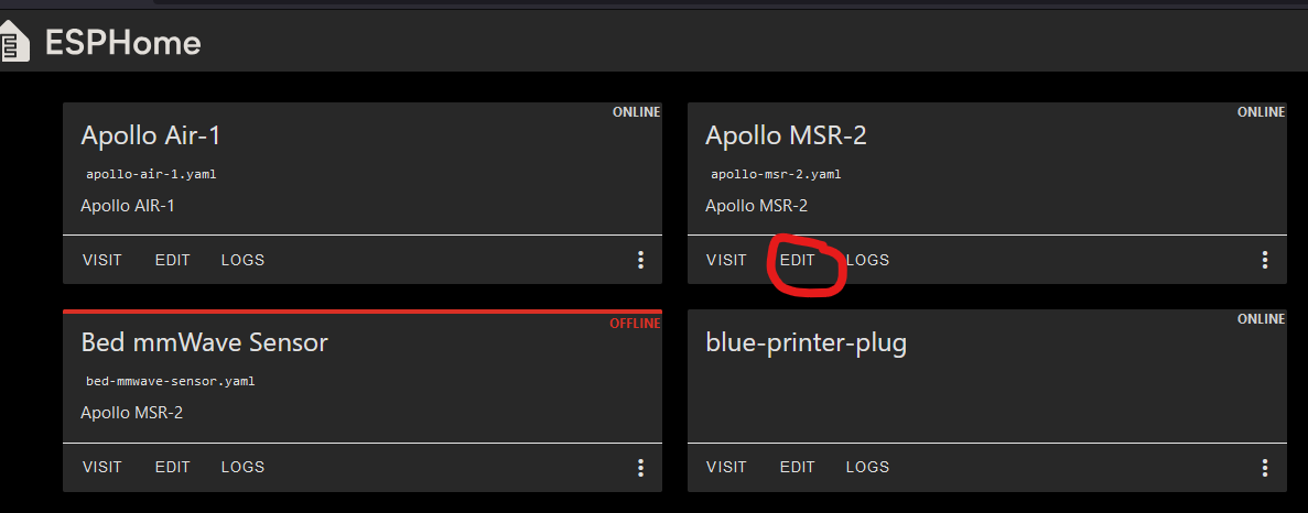
Step 1. Open ESPhome Dashboard and click edit to bring up the yaml your sensor is currently using.

You will see some YAML code here and you do NOT want to touch anything above line 20. If you need to, click your cursor at the end of wifi_password and hit enter to create a new line then make sure you backspace until you are "flush" with the line numbers like how wifi: is.
Step 2. Copy the code below and paste it to line 20 in your ESPHome yaml for this device.
light:
  - platform: esp32_rmt_led_strip
    id: bed_led
    name: "Bed LED"
    pin: GPIO7
    rmt_channel: 1
    default_transition_length: 0s
    chipset: WS2812
    num_leds: 60
    rgb_order: grb
    effects:
      - pulse:
          name: "Slow Pulse"
          transition_length: 1000ms
          update_interval: 1000ms
          min_brightness: 50%
          max_brightness: 100%
      - pulse:
          name: "Fast Pulse"
          transition_length: 100ms
          update_interval: 100ms
          min_brightness: 50%
          max_brightness: 100%
      - addressable_rainbow:

You change the rmt_channel to 1 because 0 is being used by the built-in LED of the MSR-2.
Step 5. Go into home assistant and confirm you now have a new light entity called Bed LED

Step 6. Click on the name "Bed LED" circled and it will pop up a color picker. You can then choose the color wheel option to pick any color of the rainbow, or select "effect" and choose an effect.


That's all folks! Thanks to Smart Home Sellout for putting this tutorial together!
How to edit your Sensor's LUX update interval
This guide will show you how to edit the lux updates down to 3-5 seconds.
Your sensor is defaulting to 60 seconds for updates to the state of the lux sensor. This is the default for all esphome devices using lux because it uses less Wi-Fi airtime fairness which means it is less chatty to your Wi-Fi AP or router. I would not personally go below 5 seconds.
1. Open the Esphome dashboard and click "edit" under the device you want to edit.
2. Copy this code and enter it just like shown in the next step. Make sure there are no extra spaces or any other characters it needs to look just like the example in the next step.
#LUX sensor update interval
sensor:
  - platform: ltr390
    id: !extend ltr_390
    update_interval: 5s
3. Paste the code you copied in step 2 below your sensor's existing yaml as shown below.
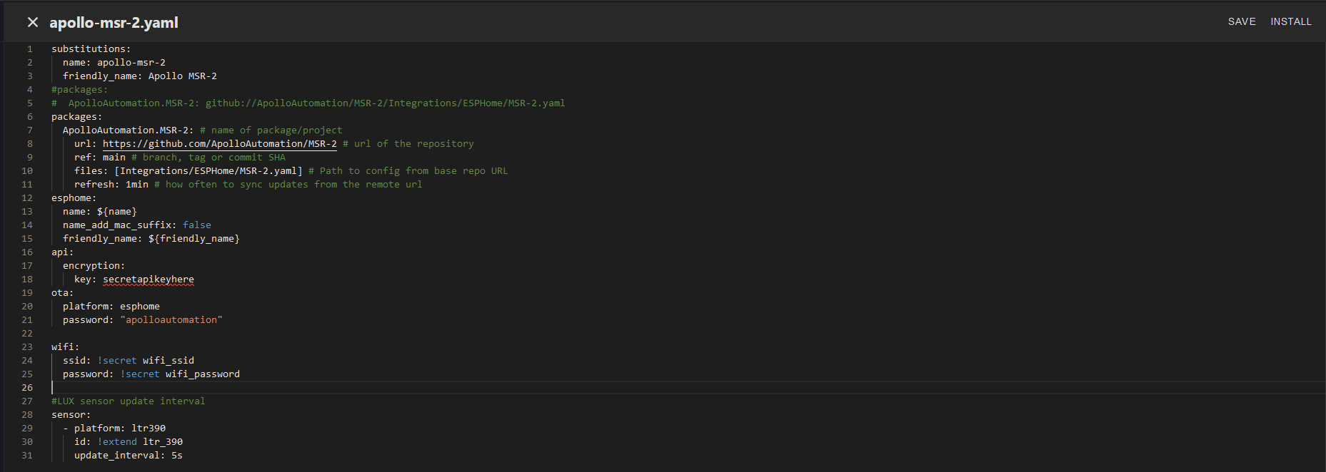
4. Click "SAVE" and then click "INSTALL" as shown in the image above. Once that is finished your sensor should now be reporting at your new update_interval such as 5 seconds!
F.A.Q. ~ Frequenty Asked Questions
This is where our most frequently asked questions will be for now!
Question:
How much power do your sensors use?
Answer:
All apollo sensors use 1amp or less, some of them 350-500mA.
Question:
What all can the MSR-2 LD2410B mmWave sensor go through?
Answer:
It can reliably go through drywall.
Question:
My MSR-2 is triggering and no one is there.
Answer:
We have seen this happen before - please first try to restart your radar, then factory reset your radar, then try a factory firmware flash. We also see success with users re-seating their LD2410B mmWave sensor.
Question:
How do I reset my Wi-Fi?
Answer:
Plug in your device then hold down the boot button for 10 seconds. The Wi-Fi credentials should be reset and it will broadcast its hotspot again.
Question:
My lux sensor doesn't seem to be working how do I fix it?
Answer:
The default update_interval is 60 seconds which isnt great for automations revolving around measuring lux values. Please follow this short guide to edit the lux update_interval down to a more responsive 3-5seconds.
Question:
Do I need to push the "Clean" button for my Air-1 or setup an automation for it?
Answer:
No, your Air-1 will self-clean once a week per this recommended documentation from the manufacturer.
Question:
Answer:
Troubleshooting Suggestions:
If your gates are acting strangely and reporting much more energy than they should, make sure there is no tension on the usb cable. One user reported still energy in gates 2 and 3 until the tension was removed from the cable.